Use the Size tab to:
Customize the ClearanceCube offset along each axis
Define a ClearanceCube for a measurement routine that does not use a CAD model
Customize the ClearanceCube offset along each axis

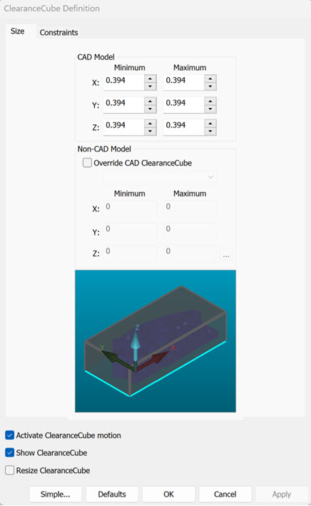
ClearanceCube Definition dialog box - Size tab
CAD Model area - This area sets the size of the ClearanceCube at a offset distance from each of the six sides.
Minimum XYZ boxes - These boxes set the offset distance of the ClearanceCube away from the XMINUS, YMINUS, and ZMINUS sides.
Maximum XYZ boxes - These boxes set the offset distance of the ClearanceCube away from the XPLUS, YPLUS, and ZPLUS sides.
Define a ClearanceCube for a measurement routine that does not use a CAD model
Non-CAD Model area - You can use this area to define the size of a ClearanceCube for a measurement routine that does not have a CAD model.
To define a ClearanceCube for this type of measurement routine, select the Override CAD ClearanceCube check box. If you have not met this option's requirements, PC-DMIS shows the following message, listing the conditions that you must complete before you can override the ClearanceCube:
Override CAD ClearanceCube can be done when the following items are completed:
1. An alignment exists in the Measurement Routine.
2. CAD Equals Part has been set.
To set CAD Equals Part, select: Operation | Graphic Display Window | CAD Equals Part.
Override CAD ClearanceCube message
To resolve this message, follow these steps:
Create at least one alignment (other than STARTUP) in the measurement routine. For instructions on how to create an alignment, see "Creating and Using Alignments".
Set the CAD = Part option as described in the message (even though you do not have a CAD model). For more information on how to set this option, see "Equating CAD to Measured Part Data".
To define the size of the ClearanceCube:
In the list underneath the Override CAD ClearanceCube check box, select an alignment ID.
Do one of the following:
Manually type the location values for the ClearanceCube in the Minimum XYZ and Maximum XYZ boxes relative to the selected alignment.
Enable PC-DMIS to automatically create the location values. (This option is available only when PC-DMIS is in Online mode.) To do this:
Click the read
points ( ) button. This message appears:
Position probe (tip) to define ClearanceCube corner (Front Lower Left).
where tip is the probe tip at the cursor's current location in the Edit window.
Ensure that the probe tip you
want to use is the one that appears in the message. If you want to change
the probe tip, click Cancel, select the desired
probe tip in the Edit window, and click the read points ( )
button again.
Position the probe tip at the front lower left corner of the ClearanceCube and then click OK (or press the Done button on the jog box). This message appears:
Position probe (tip) to define ClearanceCube corner (Rear Upper Right).
The (tip) in the message above is the probe tip at the cursor's current location in the Edit window.
Position the probe tip at the rear upper right corner of the ClearanceCube and then click OK (or press the Done button on the jog box). PC-DMIS automatically fills in the values in the Minimum XYZ and Maximum XYZ boxes and draws the ClearanceCube.
Preview Area - The CAD preview area shows a preview of the ClearanceCube based on your offset modifications.
Activate ClearanceCube Motion - For details on this check box, see "Activating ClearanceCube Motion".
Show ClearanceCube - For details on this check box, see "Activating ClearanceCube Motion".
Resize ClearanceCube - For details on this check box, see "Activating ClearanceCube Motion".
Simple - This button sets the ClearanceCube Definition dialog box back to its initial simplified state.