
You do not need to create an arm-to-arm map for every extension. While a single map is insufficient for good accuracy, you can obtain good accuracy with two maps. It's better to do one mapping of the short extension followed by one with the long extension. This step will help you build the AUTO_MAPS.PRG routine for the recommended two maps.
Define Parameter Sets for Probe Extensions in AUTO_MAPS.PRG
Access AUTO_MAPS.PRG and place the Edit window in Command mode.
Start with the ARM1_1 probe. Access the Measure Probe dialog box (Insert | Hardware Definition | Probe | Measure button) for that probe.
Define all the parameters you need in this dialog box to create a new arm-to-arm mapping of that probe.
Choose Replace closest map in the Wrist Calibration area.
In the Parameter Sets area, give the set a name by typing in the Name box the name of the probe with a "_MAP" suffix appended (for example, "ARM1_1_MAP").
Example of Parameter Set creation
Click Save. A parameter set is created for ARM1_1 probe. Click OK to close the message box.
Repeat 2-6 for each probe, creating a parameter set for each.
When finished, you should have these six parameter sets:
ARM1_1_MAP - For the probe named ARM1_1 (the short extension on arm 1)
ARM1_2_MAP - For the probe named ARM1_2 (the medium extension on arm 1)
ARM1_3_MAP - For the probe named ARM1_3 (the long extension on arm 1)
ARM2_1_MAP - For the probe named ARM2_1 (the short extension on arm 2)
ARM2_2_MAP - For the probe named ARM2_2 (the medium extension on arm 2)
ARM2_3_MAP - For the probe named ARM2_3 (the long extension on arm 2)
You only need to create parameter sets for the number of extensions you have on each arm. For example, if you only had two extensions on each arm, you would end up with a total of four parameter sets.
This means, you can now use an AUTOCALIBRATE command to calls one of these parameter sets. When the AUTOCALIBRATE statement executes, PC-DMIS will generate a new arm-to-arm mapping with all settings stored in the called parameter set.
Add Preliminary Commands into AUTO_MAPS.PRG
Access AUTO_MAPS.PRG.
Add in a TEMPCOMP command (temperature compensation) for arm 1. If you're calibrating inside of a climate-controlled environment, the temperature compensation commands aren't needed. See "Compensating for Temperature" and "Using Temperature Compensation with Multiple Arm Calibration".
Add a MOVE/SYNC command.
Add in a TEMPCOMP command for arm 2.
Type a MOVE/SYNC command after the TEMPCOMP command blocks.
Type a LOADPROBE/ARM1_1 command to load the probe with the short extension on arm 1. Assign the command to arm 1.
Type a LOADPROBE/ARM2_1 command to load the probe with the short extension on arm 2. Assign the command to arm 2.
Type a LOADPROBE/ARM1_3 command to load the probe with the long extension on arm 1. Assign the command to arm 1.
Type a LOADPROBE/ARM2_3 command to load the probe with the long extension on arm 2. Assign the command to arm 2.
Insert AUTOCALIBRATE Commands for Short and Long Probe Maps in AUTO_MAPS.PRG
Access AUTO_MAPS.PRG.
Place the cursor after the LOADPROBE commands for the short probes.
Insert an AUTOCALIBRATE command (choose Insert | Calibrate | AutoCalibrate Probe).
Press F9 on the command. The Calibrate Probe dialog box appears.
In the Parameter set list, choose the parameter set for the short probe on arm 1. This is ARM1_1_MAP.
Click OK. The command updates to use the selected parameter set.
Assign the command to arm 1.
Repeat 3-6 for the short probe on arm 2. This is ARM2_1_MAP. Assign the command to arm 2.
Place the cursor after the LOADPROBE commands for the long probes.
Repeat 3-6 for the long probe on arm 1. This is ARM1_3_MAP. Assign the command to arm 1.
Repeat 3-6 for the long probe on arm 2. This is ARM2_3_MAP. Assign the command to arm 2.
Type a MOVE/SYNC command at the end of the routine.
Insert Moves Between Short and Long Probe Maps in AUTO_MAPS.PRG
After the AUTOCALIBRATE commands for the short probes and before the LOADPROBE command for the long probes, type a MOVE/SYNC command.
After the MOVE/SYNC command, ensure that the tips' angles are adjusted appropriately for drop off at their respective probe changers. You can do this by inserting moves appropriate to your machine's dimensions and arm and probe changer setup.
This completes the information needed for the AUTO_MAPS.PRG.
Your routine should now be organized like this:
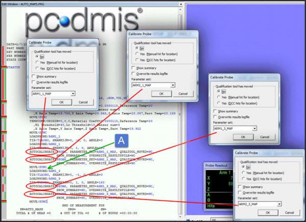
Sample AUTO_MAPS.PRG Routine. Safety moves are inserted after the MOVE/SYNC, indicated by green arrow (A).
Notes on using AUTO_MAPS.PRG
You would run this routine to recreate the arm-to-arm mapping in these instances:
Whenever your normal maintenance schedule requires that your mappings should be updated.
Whenever you need to use an entirely new probe. In that case, you would need to add in the LOADPROBE statements for the new probe.
Whenever you wrist is remounted (for example, after a technician adjusts its electronic compensation).
Whenever data is lost or corrupted or you're not sure if the mapping is correctly generated.
Whenever a room situation changes that alters the thermal compensation (for example, if moving the machine out of a climate controlled room).
Whenever the physical structure of the machine changes.
Before you run this routine, delete old maps. Use the View | Delete maps button located in the Wrist calibration area of the Measure Probe dialog box to do this.
If you're using long extensions, and you aren't running at maximum speeds, expect a minimum of 3-4 hours to run the entire routine. This time is just an estimate, as it depends on your individual machine dimensions, the length of the extensions, and speed percentage used.
The next step provides information on adding commands to AUTO_UPDATE.PRG.