Properties dialog box – Module tab
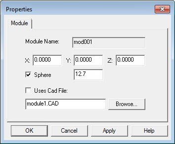
The Module tab in the Properties dialog box lets you specify the location, sphere size, and CAD files of the module.
Module Name - Shows the name given to the module. It identifies the module when you create a fixture.
XYZ - Determine the measured offsets of the module from the column sphere center to the contact point (or, if the contact point on the module is a sphere, to the center of that sphere). The end point of the module is either the center of the module sphere, if any, or any point that has been defined on or outside the module itself in the case of a "netpad" module.
Sphere - Determines whether the point of contact on the module is a sphere. The box to its right determines the diameter of the "point of contact" sphere.
Uses Cad File - Determines whether PC-DMIS should associate a custom CAD model with this module for display in the Graphic Display window. To create a custom CAD model, see the "To Create a Custom CAD Model" topic. If you select this check box, you must specify the CAD name in the Uses Cad File box.
The box underneath the Uses Cad File check box defines the CAD file that you are using to represent this module. You can use the Browse button to locate the CAD file on your computer. The selected file name appears in the box. See the "To Create a Custom CAD Model" topic for information on how to create a CAD file to use with PC-DMIS.
Click Apply to apply any changes that you made for this module.
Click OK when you are done changing all fixture properties.