The Compare to CAD thickness colormap processing can be very time-consuming when working with a large pointcloud (greater than one million points). We recommend that you filter the pointcloud prior to performing the Compare to CAD operation. For details on filtering a pointcloud, see "FILTER" in this documentation.
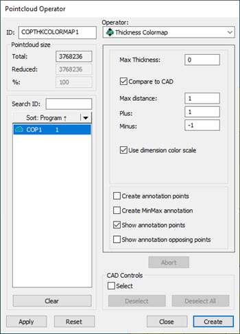
You can create a thickness colormap of a Pointcloud data object in comparison to a CAD model. In this case, from the Pointcloud Operator dialog box, select the Compare to CAD check box.
When you select CAD faces for a Thickness Colormap compared to CAD, PC-DMIS uses both sides of the material to compute the thickness; however, PC-DMIS only colors the data for the selected faces.
PC-DMIS computes the deviation of the data object thickness in comparison to a CAD model.
The software colormaps the Pointcloud data object used for the comparison to CAD to show the deviations.
To do this:
From the Pointcloud Operator dialog box, select ThicknessColormap from the Operator list.
Choose the corresponding Pointcloud data object.
Enter the Max Thickness. The software does not evaluate any data value greater than this value.
Click Compare to CAD and enter the appropriate tolerance values in the Plus Tol and Minus Tol boxes. You must use a minus sign when you enter a negative number.
Enter the Max distance. PC-DMIS uses the data within this distance from the CAD model for the colormap.
Click Apply.
Create annotations. For details on how to create annotation points for the Thickness Colormap operator, see "Thickness Colormap Annotations".
Click Create.
More:
Show the Thickness Colormap in the Report
Thickness Colormap Annotations
Show Annotation Opposing Points