For a visual example of these parameters, consult the diagrams below.
Flush - This box determines the height difference between two mating sheet metal parts. Whether or not the flush value is positive or negative depends on whether it’s higher or lower than the "Master" side.
Gap - This box determines the distance (in the same plane) between two mating sheet metal parts.
Indent - The indent specifies the distance from the gap’s edge at which PC-DMIS measures the flush.
Spacer - This is a circle at the indent point used to calculate the surface normals used in the calculation.
Gap Dir (Vector) - These boxes in the Feature Properties area define the direction of the gap.
Flush and gap diagram
Key:
1 - Gap
2 - Indent
3 - Flush (negative flush is shown at left)
4 - Master side
5 - Cut Vector
6 - Spacer
The "Master" side is always to the left of the scan/gap direction.
The direction of the scan is controlled by the specified Cut Vector and not the direction of the laser stripe.
Direction of scan
(A) - Masterside (B) - Scan motion
The "Master" side is always to the left of the Cut Vector.
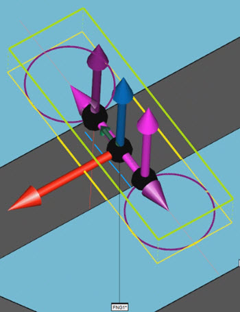
Sample Flush and Gap Auto feature in the Graphic Display window. This shows the indent (red lines), spacer (purple circles), depth (blue line), horizontal clipping region (yellow lines), vertical clipping region (green), the view vector (blue arrow), and the cut vector (red arrow).