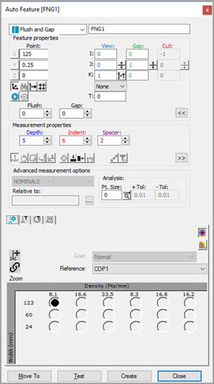
Auto Feature dialog box - Flush and Gap
Flush and Gap measures the height difference between two mating sheet metal parts (the Flush) and the distance between two mating parts (the Gap).
To measure a Flush and Gap using a laser sensor, access the Auto Features dialog box and select Flush and Gap. The dialog box automatically expands the Extended sheet metal options area. This area provides XYZ position boxes and IJK vector boxes for the Master and Gauge points. Follow one of the procedures below.
With CAD Data
Load a CAD model.
Click on the Master side.
Click on the Gauge side.
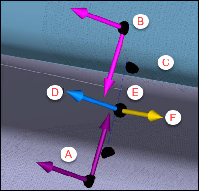
A - Master
B - Gauge
C - CAD learned curves
D - View vector
E - Depth line
F - Cut vector
These points must be on the reference "flat" surfaces, where PC-DMIS sets the planes used to calculate flush, and not on the curves.
PC-DMIS performs these calculations in the background:
The software learns the theoretical Flush.
The software learns the curves from the CAD model.
The software learns the point coordinate and vectors for both the Master and Gauge sides of the gap.
The software applies the defined Depth value, and, after piercing the curves, it calculates the theoretical gap at the specified depth.
The software also calculates the cut vector (along the rail) and the Gap direction (crossing the rail).
Set the Indent and the Spacer values so that they only include points on the flat surfaces and not points on the curved portion.
Set other parameters as needed. See "Flush and Gap Specific Parameters".
Enter the necessary information in the Probe Toolbox tabs. Cycle through the Laser Scan, Laser Filtering, and Laser Clipping properties tabs to enter the information.
If desired, click the Test button to test the feature.
WARNING: When you do this, the machine moves. To avoid injury, stay clear of the machine. To avoid hardware damage, run the machine at a slower speed.
Click the Create button and then Close.
Flush and Gap CAD Selection Capability
The ability to re-click the first CAD point on a selected surface is often a requirement when you define or re-define a measurement routine.
Other than the Master Side Point and the Edge Vector, PC-DMIS displays the first point you click in the Graphic Display window, as a black circle centered in the picked point. The software also highlights the selected surface.
Sometimes, the Master Side Point found is in a wrong surface boundary location, and the software requires you to click the point again. The following describes two ways to do this:
If the desired Master Side Point is on the edge of the highlighted surface, it's sufficient to just re-click a point on the surface very close to the edge.
If the desired Master Side Point doesn’t lie on the highlighted surface, you can click the drawn circle area to reset the interface. PC-DMIS is then ready for you to re-take the first point. To help re-define the new surface selection, PC-DMIS leaves the previous surface highlighted. See the example pictures below:
Example of Flush and Gap Auto feature CAD selection capability
Without CAD Data
Use the Laser tab of the Graphic Display window to move the machine to the gap location.
Click the Read Point from Position button.
Manually type all of the theoretical XYZ and IJK values. These include the Flush and Gap Point, the View Vector, Gap Dir (gap direction), Master Pnt (master point), Gauge Pnt (gauge point), Master Vec (master vector), and Gauge Vec (gauge vector).
Note that when you change some parameters, and you don't have any CAD data, PC-DMIS adjusts some parameter values automatically. For information, see "Automatically Adjusted Flush and Gap Values".
Set the Indent and the Spacer values so that they only include points on the flat surfaces and not points on the curved portion.
Set other parameters as needed. For information, see "Flush and Gap Specific Parameters".
Enter the necessary information in the Probe Toolbox tabs. Cycle through the Laser Scan, Laser Filtering, and Laser Clipping properties tabs to enter the information.
If desired, click the Test button to test the feature.
WARNING: When you do this, the machine moves. To avoid injury, stay clear of the machine. To avoid hardware damage, run the machine at a slower speed.
Click the Create button and then Close.
More:
Flush and Gap Specific Parameters
Flush and Gap Command Mode Text
Flush and Gap Graphical Analysis