
Mesh toolbar
The Mesh toolbar provides all mesh operations, features, and functions. It is accessible from the View | Toolbars | Mesh menu.
The Mesh license must be enabled to use or view this option.
The following options are available from this toolbar:
 Mesh - This button opens the Mesh
Command dialog box that you can use to create mesh features from
any number of pointclouds. For details on this dialog box and how to create
mesh features, see the "Creating
a Mesh Feature" topic.
Mesh - This button opens the Mesh
Command dialog box that you can use to create mesh features from
any number of pointclouds. For details on this dialog box and how to create
mesh features, see the "Creating
a Mesh Feature" topic.
 Mesh Operator - This button opens the Mesh Operator dialog box that you can use to perform
different operations on a Mesh and other Mesh operator commands. For details
on the dialog box and how to create mesh operators, see the "Creating
a Mesh Operator" topic.
Mesh Operator - This button opens the Mesh Operator dialog box that you can use to perform
different operations on a Mesh and other Mesh operator commands. For details
on the dialog box and how to create mesh operators, see the "Creating
a Mesh Operator" topic.
 Portable
Scanning Widget - This button displays the Portable
Scanning Widget toolbar. When you connect to a portable device,
and the active probe is a laser scanner, PC-DMIS automatically shows the
Portable Scanning Widget toolbar. For details
on the Portable Scanning Widget toolbar, see
"Portable
Scanning Widget Toolbar" in the PC-DMIS Portable documentation.
Portable
Scanning Widget - This button displays the Portable
Scanning Widget toolbar. When you connect to a portable device,
and the active probe is a laser scanner, PC-DMIS automatically shows the
Portable Scanning Widget toolbar. For details
on the Portable Scanning Widget toolbar, see
"Portable
Scanning Widget Toolbar" in the PC-DMIS Portable documentation.
 Mesh Cross Section - This button opens the Mesh Operator dialog box that you can use to create
a cross section from an existing mesh. Click the drop-down arrow to display
the Mesh Cross Section toolbar:
Mesh Cross Section - This button opens the Mesh Operator dialog box that you can use to create
a cross section from an existing mesh. Click the drop-down arrow to display
the Mesh Cross Section toolbar:
For details on Mesh cross sections and using the Mesh Cross Section toolbar, see "Mesh CROSS SECTION Operator" in this documentation.
 Import Mesh in STL Format - This button opens
the Mesh Import Data dialog box that you can
use to import an STL mesh data file. If a Mesh object does not exist in
the PC-DMIS Edit window, then a new Mesh object is created, and the software
imports the STL data. If a Mesh object already exists in the PC-DMIS Edit
window, then the software adds the STL data to the Mesh object.
Import Mesh in STL Format - This button opens
the Mesh Import Data dialog box that you can
use to import an STL mesh data file. If a Mesh object does not exist in
the PC-DMIS Edit window, then a new Mesh object is created, and the software
imports the STL data. If a Mesh object already exists in the PC-DMIS Edit
window, then the software adds the STL data to the Mesh object.
For details, see the "Mesh IMPORT Operator" topic.
 Export Mesh in STL Format - This button opens
the Export Mesh Data dialog box that you can
use to export a Mesh in an STL, ASCII, or STL Bin file format.
Export Mesh in STL Format - This button opens
the Export Mesh Data dialog box that you can
use to export a Mesh in an STL, ASCII, or STL Bin file format.
For details, see the "Mesh EXPORT Operator" topic.
![]() Empty a Mesh - This button empties the first
mesh relative to the cursor position in the Edit window.
Empty a Mesh - This button empties the first
mesh relative to the cursor position in the Edit window.
Once you apply this command to a Mesh, there is no way to restore the Mesh data. You cannot click Undo to restore the lost data.
For details, see the "Mesh EMPTY Operator" topic.
 Reset Mesh - Use this button to revert all Mesh
SELECT operations and return the original Mesh object. For details on
the Reset Mesh operator command, see "Mesh
RESET Operator" in the PC-DMIS Laser documentation.
Reset Mesh - Use this button to revert all Mesh
SELECT operations and return the original Mesh object. For details on
the Reset Mesh operator command, see "Mesh
RESET Operator" in the PC-DMIS Laser documentation.
 Select Mesh - Use this button to select and delete
a subset of triangles contained in the mesh data object. When you use
this button, the selection method uses a polygon to remove triangles in
the 3D view.
Select Mesh - Use this button to select and delete
a subset of triangles contained in the mesh data object. When you use
this button, the selection method uses a polygon to remove triangles in
the 3D view.
The Select Mesh button option differs from the use of the Mesh Select operator from the dialog. When you click this button, PC-DMIS immediately applies the function but does not add a Select command. To create the command, open the Mesh Operator dialog and choose the Select function.
After you click this button:
Click in the Graphic Display window to define the polygon vertices.
Press the Delete key to delete the last vertex.
Double-click your left mouse button or press the End key to close the polygon selection. PC-DMIS removes the portion of the mesh enclosed by the polygon.
Press the Esc key to abort.
For details, see the "Mesh SELECT Operator" topic.
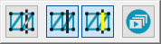
 Colormap a Mesh: This button opens the Mesh Operator dialog box that you can use to create
a Mesh COLORMAP operator. For details, see the "Mesh
COLORMAP Operator" topic.
Colormap a Mesh: This button opens the Mesh Operator dialog box that you can use to create
a Mesh COLORMAP operator. For details, see the "Mesh
COLORMAP Operator" topic.
The Colormap a Mesh operation applies a colored shading to the selected mesh. PC-DMIS shades the model according to the deviations of the mesh compared to the CAD. The Colormap a Mesh operation uses the colors defined in the Edit Dimension Colors dialog box and the tolerance limits specified in the Upper tolerance and Lower tolerance boxes. For details on the Colormap a Mesh operator, see the "Mesh COLORMAP Operator" topic in the PC-DMIS Laser documentation.
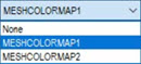
You can create multiple colormaps in a PC-DMIS measurement routine. However, only one is active. The last colormap that was applied and created (pointcloud surface colormap or mesh colormap), or the last one executed, is always the currently active colormap. You can also select which colormap is the active one from the Colormaps list box. When you activate a new colormap, PC-DMIS displays its associated scale with tolerance values and any annotations in the Graphic Display window.
To do this, click the Colormaps list box and select the colormap from the list of defined colormap operators:
Click the drop-down arrow to display the Mesh Colormap toolbar:

The Mesh Colormap toolbar allows you to select between the Colormap a Mesh and Thickness Colormap options. For details on the Thickness Colormap option, see "Thickness Colormap" in this documentation.
 Mesh Alignment: This button opens the Mesh/CAD Alignment dialog box that you can use
to create Mesh-to-CAD alignments.
Mesh Alignment: This button opens the Mesh/CAD Alignment dialog box that you can use
to create Mesh-to-CAD alignments.
For details, see the "Mesh ALIGNMENT" topic.
 Receive a mesh from OptoCat: When you click
this button ON, PC-DMIS waits to receive a mesh from the OptoCat application.
When the Receive a mesh from OptoCat button
is ON, it has a darker background color:
Receive a mesh from OptoCat: When you click
this button ON, PC-DMIS waits to receive a mesh from the OptoCat application.
When the Receive a mesh from OptoCat button
is ON, it has a darker background color:  .
For details on how this works, see the "Receive
a Mesh from OptoCat" topic.
.
For details on how this works, see the "Receive
a Mesh from OptoCat" topic.
More: