Interface DLL - WENZEL.DLL
PCDLRN.INI Section header title - [WENZEL]
This interface requires three RS-232 comm ports for the CMM, the PH9, and the function keys on the Jog Box.
Your original computer usually provides a five port comm port card that typically connects to a large blue cable with five, 25-pin connector ends. Trace these cables back to the controller and look for the controller, probe head and jog box connections. Label them accordingly.
You should only have the controller, probe head and jog box connected.
You can use the RS232/2 connection (or the RS232-J connection for Pantec systems) for the function keys on the jog box but you must use a null modem cable.
You must use the standard 25 pin to 25 pin extension cable that came with the controller on the PHC10-2 and then connect a serial 25 pin to 9 pin cable to the comm port.
Potential communication errors may occur if you use a single 25 pin to 9 pin cable between the PHC10-2 and the comm port. Alternatively, you can use the single 25 pin to 9 pin cable by Assmann (AK124-3, CABLE ASSY DB09 TO DB25 SHLD 3M) found here: https://www.digikey.com/products/en?keywords=AE1032-nd
You can find the comm port settings as a configuration menu option in the original software (typically OpenDMIS). If you run the original OpenDmis software, run the "Neptune driver" utility located in the Window's task bar to try and get this information. Set the RS232 parameters in PC-DMIS with the same settings.
The Wenzel CMM communication baud rate to the controller is typically 115200.
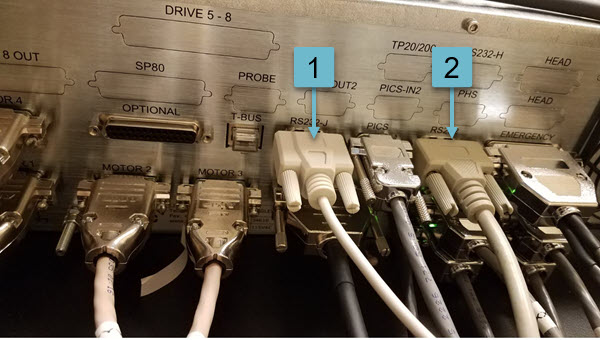
The image below details the RS232 assignments for a Wenzel (Pantec) controller that is connected via Ethernet.
Wenzel (Pantec) controller RS232 assignments:
1 = 9 pin female null mode cable needed for communications to the jog box function keys
2 = 9 pin female serial cable needed for communications to the Wenzel/Pantec controller
The controller can still communicate via RS232 even when it's using the Ethernet. Connect the RS232 serial cable to the 9-pin port labeled RS233. This is required since PC-DMIS only supports RS232 communication with the Wenzel controller. You can connect the Ethernet and RS232 cables at the same time.
There should already be a cable connected from the Renishaw probe head controller to the computer. Use this same cable for communications in PC-DMIS to the probe.
On newer machines, no machine parameters are required from the original systems. If you have an older machine that does require the machine parameter files from the original system, set the SendParameters option to True.
If your controller was initialized by a different software, you MUST power it down and then restart it before PC-DMIS can communicate with it.
The current version is 1.68
Interface Specific Options
The following Wenzel controller options exist for the PCDLRN.INI file:
Acceleration = 200 - This defines the acceleration value for the machine acceleration parameter.
AvoidResetOnHit = False - Set this to True if there is a pause after each hit to help optimize the hit process.
CMM = COM1 19200 N,8,1 - This defines the CMM controller communication parameter. While some controllers have a baud rate of 115200, the newer WP2030 controller uses a baud rate of 38400.
CmmCircularMoves = 1 -
DCC_Retract = True - When set to True, the controller uses the jog box retract distance. Some controllers use the jog box retract distance for DCC. The retract value for a DCC Measure must be sent to the controller when you change modes.
HomeAccelFast = 200 - This entry defines the homing acceleration speed when SlowHomeMove = False.
HomeAccelSlow = 50 - This entry defines the homing acceleration speed when SlowHomeMove = True.
HomeDelay = 1 - This defines the delay in seconds between sending a reset command and the subsequent homing command. On some machines, you must increase this value to get a consistent homing of the machine.
HomeSpeedFast = 100 - This entry defines the homing speed when SlowHomeMove = False.
HomeSpeedSlow = 30 - This entry defines the homing speed when SlowHomeMove = True.
IgnoreSoftLimitsInManual = True - Set to False on newer controllers when the controller reset (M949=2) is called too frequently which causes shaky movements and the light on the PH10 probe to flash. Consequently, you have to move the probe head to a working measurement area to stop it.
JogBoxOptions = 0 - Set to 1 to not trigger a feature execution when you press F4. Set to 2 to reset the TP200 damping when going out of soft limit.
JoyAccel = 100 - If the CMM overtravels by a few inches before stopping, try cutting this in half to see how it responds and then adjust from there if necessary.
JoySpeedFast = 100 - This entry defines the jog speed when in Fast Jog mode.
JoySpeedSlow = 20 - This entry defines the jog speed when in Slow Jog mode.
MaxControllerMoves = 10 - This defines the maximum number of commands sent to the controller at one time.
MaxSpeed = 50.0 - This option sets the maximum speed for the CMM.
MinPreHitDist = 0 - This entry sets the minimum allowed prehit distance value to the controller. You can use this when you encounter errors using small prehit distances.
MinRotabMove = 0.5 - This defines the minimum rotate request that the software sends to the controller.
NoDccForNewControllerHome = False - Set to True when you use the 2040 controller and you get a homing error.
PH9 = COM0 4800 N,8,1. PH9 - This defines the PH9 parameters for the controller communication.
PreInit = False - This entry determines if the controller sends a pre-initialization sequence. On some older controllers this was a requirement. Typically you should set this entry to False.
RotabspeedMax = 0 - This defines the maximum rotary table speed. If there is a rotary table, this should be set to 300 or the known maximum rotary table speed.
RotabspeedMin = 1 - This defines the minimum rotary table speed.
ScaleX = 1.0 - This value specifies the scale factor for the X axis. Change this value to accommodate any scale stretch.
ScaleY = 1.0 - This value specifies the scale factor for the Y axis. Change this value to accommodate any scale stretch.
ScaleZ = 1.0 - This value specifies the scale factor for the Z axis. Change this value to accommodate any scale stretch.
The default Scale value is 1.0.
SendParameters = False - When you must download the parameter files on machines when the EPROM data is unreliable, set this value to True. When you set this to True, you must provide PC-DMIS with the original startup file from the Wenzel software to perform correctly.
You must copy these four files from the Wenzel software directories into the PC-DMIS directory: WPMACH.PMC, WPSW.PMC, WPDAT.PMC, and WPGO.PMC.
The original file names may be different, for example "WPGO20.PMC" instead of "WPGO.PMC ". If this is the case, you must rename them with the corresponding file names listed above.
If this parameter is set to True and the servos are on, you may have problems when you restart PC-DMIS. To prevent any problems from occurring, always press the ESTOP and then release it before you restart PC-DMIS.
SlowHomeMove = False - Set this entry to True to slow the machine motion. This is often necessary if the CMM causes an error during homing due to it hitting the "end-of-axis" too hard.
Terminal = COM0 4800 N,8,1 - This defines the Wenzel HT400 jog box communication parameters.
TimerUpdateInterval = 50 - This entry defines how frequently the system updates the scales readouts in msec.
TP200DampingOptimization = False - Set to True to enable TP200 with damping mode. The normal implementation uses the controller reset (M949=2). Often though, damping optimization uses the probing On and Off commands (M916=1|0) instead.
TP200DampingSwitchStr - For TP200 optimization, you can define a key for the EB-Elektronik HT400 jog box that switches damping on/off. When you run PC-DMIS in manual mode, damping is off by default (probing is enabled). You can setup the jog box key to switch damping on for long moves etc. You can use the light on the PH10 as a visual feedback to determine when damping is on or off. Note that when damping is on, probing is disabled.
UseLFForACK = False - This entry is obsolete and is no longer used.
UsingControllerVectors = False - When set to True, PC-DMIS uses the hit vectors maintained by more recent controllers. Otherwise, PC-DMIS computes the hit vectors.
UsingHT400JogBox = False - Set to True to let the SB-Elektronik HT400 jog box use function keys with PC-DMIS. For details on the EB-Elektronik HT400 jog box function keys, see "Additional Notes".
WaitBeforeMeasure = False - Set this value to True if a problem occurs with the Find Hole option.
WaitMoveTimeout = 0.5 - When the controller sends a move command, PC-DMIS waits until the CMM starts moving before it checks for the move complete command. If the CMM is already in the commanded position however, the CMM does not move. This option determines how long the controller waits for the CMM to start moving before sending the next command. You should only change this value if the CMM hangs at the beginning of DCC.