To set up your rotary table:
Start PC-DMIS.
Create a new measurement routine. It should have the same Measurement Units (IN or MM) as your machine to help debug problems, but this is not mandatory.
Select the machine of interest from the list on the Settings toolbar.
You should select the correct machine from the Settings toolbar whether you create paths for calibration, rotary table configuration, or general measurement routines.
Select Operation | Calibrate/Edit | Rotary Table to open the Rotary Table Setup dialog box.
You can also access the Rotary Table Setup dialog box from the Edit | Preferences | Rotary Table Setup menu option.
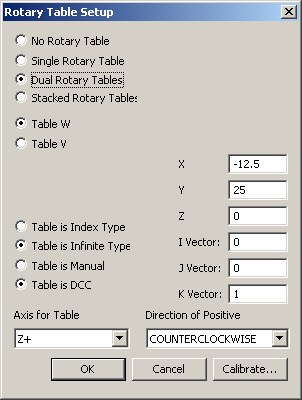
Rotary Table Setup dialog box
From the upper-left area of the dialog box, select the type of rotary table configuration:
No Rotary Table - A rotary table is not being used.
Single Rotary Table - A single rotary table is being used.
Dual Rotary Table - Two rotary tables, not necessarily stacked, are being used.
Stacked Rotary Tables - Two stacked rotary tables are being used.
For Dual and Stacked Rotary Table configurations, and if you select either the Table W or Table V option, you must specify the parameters for each table. The settings for each table are independent.
For each rotary table, select either the Table is Index Type or Table is Infinite Type option.
For each rotary table, select either the Table is Manual or Table is DCC option.
For each rotary table, select the Axis for Table from the drop-down list box. Select the normal vector of the table. The software uses this axis when you define the Direction of Positive Rotation.
Specify the Axis for Table before you update the XYZ values.
Enter the nominal location of the table center in the XYZ boxes. You should enter this value in "machine coordinates", with no active tool or work offsets.
Do not update the IJK vector values directly.
Select either CLOCKWISE or COUNTERCLOCKWISE from the Direction of Positive Rotation drop-down box. CNC machines can have a left-handed relationship between the table axis vector and direction of rotation. The direction of rotation defines how the table turns when one looks "down" the Axis for Table Vector.
Enter the nominal location of the table center in the XYZ Center boxes. You should enter this value in "machine coordinates", with no active tool or work offsets.
Enter the normal vector of the table in the IJK Vector boxes.
Work offsets are assumed not to be in effect for rotary table calibration.