To calibrate your rotary table:
Create a new, empty PC-DMIS measurement routine.
If you are calibrating Dual or Stacked Rotary Tables, select either Table W or Table V before you click the Calibrate button in the Rotary Table Setup dialog box. The physical axes for both of these tables should also be set to zero. You need to complete all of the following steps for both tables.
From the Rotary Table Setup dialog box, click the Calibrate button to open the Calibrate Infinite Rotary Table dialog box.
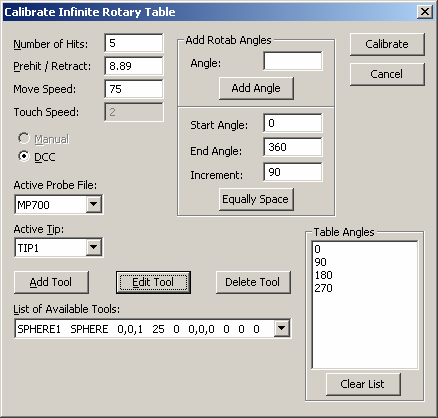
Calibrate Infinite Rotary Table dialog box
Specify the probing parameters for the calibration process. Number of Hits will be taken on the qualification tool. The Prehit/Retract value determines the distance from the hit location that the probe moves to before and after the hit is taken. The Move Speed value is a percentage of the maximum speed of the probe.
Select the Active Probe File and the Active Tip to use for calibration.
Click Add Tool to define a new calibration tool, or click Edit Tool to change an existing calibration tool. For more information, see the "Add Tool" topic in the "Defining Hardware" chapter in the PC-DMIS Core documentation. The location of the tool is at zero degrees on the rotary table in machine coordinates. To determine the tool location, jog the probe close to the "top" of the probe, read the counters, and then add or subtract the probe radius to one of the axes. The last step depends on the orientation of the probe with respect to the table.
To add a single Rotary Table angle, type the new angle value in the Angle box and then click the Add Angle button. This adds the specified angle to the Table Angles list.
To add multiple Rotary Table angles, type the respective values in the Start Angle, End Angle, and Increment boxes. Click Equally Space to add new Rotary Table angles to the Tables Angles list. Then start with the starting angle and increment up to the ending angle.
Click the Calibrate button, The commands the software uses to calibrate the rotary table are written to the current measurement routine. PC-DMIS generates measurement paths for all of the sphere positions.
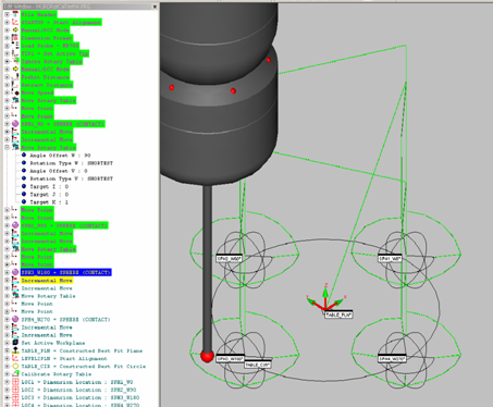
Rotary Table Calibration Path Lines and Sphere Locations
Save the current measurement routine so that it can be executed when the calibration is performed using the NC Server application.
For information on the NC Server operation, see the NC Server documentation.