PC-DMIS NC must be configured to use a wrist device in the Physical tab of the MachineDefinition dialog box.
In the Wrist area, set the number of wrist axes using the drop-down list.
For each axis, define the Axis identifier used to move the wrist.
The Reverse setting may also need to be checked to make the motion of the wrist compatible with the PC-DMIS software's expected motion.
Edit the Axes Map which provides the ordering of the machine axes in relation to the logical controller axes.
For information on the NC Server operation, see the NC Server documentation.
The wrist must be defined in the USRPROBE.DAT file or the PC-DMIS PROBE.DAT file. This file must be supplied at installation with a wrist modeled as a connection with no offsets.
The wrist must always be calibrated at each angle used for measurement. To do this, you can use the PC-DMIS software's probe calibration functionality on the Probe Utilities dialog box.
There are two methods in which the wrist may be defined, depending on your installation: Tool Point or End of Ram
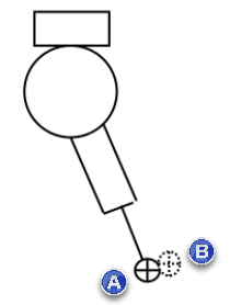
Tool Point: This method assumes the controller has the ability to predict the location of the end of the tool regardless of head angles. For example, the Siemens 840D control enables this capability with the TRAORI command. The length of each tool, including the measuring probe, is known to a high degree of accuracy, but the remaining errors can be removed by calibration. Do not zero out the tool offsets. Model the probe as a single ball of the same nominal size as the stylus with the No Offset wrist. Only a single stylus may be used. The probe is calibrated at the angles of interest using PC-DMIS probe calibration. The stored calibration values consist of small errors in the XYZ location of the stylus and the stylus diameter.
Tool Offset known by Controller
(A) - Controller Offset
(B) - Calibrated Offset
End of Ram: This method requires an accurate model of the wrist in the probe database. It is similar to the method used to calibrate CMM wrists. The Probe Offsets maintained in PC-DMIS are now from the end of the machine ram to the ball center of the stylus. The tool offset for the probe in the control, if any, is zeroed before probe calibration. A calibration measurement routine is created for the angles of interest, exported, and executed on the NC machine.
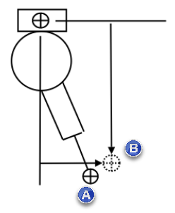
Tool Offset from Ram Reference Point
(A) - Nominal Offset from Head and Probe Models
(B) - Calibrated Offset