

Measured Two-Point Round Slot button (Left)
Measured Two-Point Square Slot button (Right)
Similar to creation of "single-point" measured circle features, portable devices take only two hits, one on each end of the slot to create a measured square or round slot feature. This is termed a "two-point" slot. This is useful when you attempt to measure a slot with a probe whose sphere size is larger than the slot's diameter and therefore cannot fit entirely into the slot to take the usual minimum number of hits required for a measured slot. In this case, PC-DMIS creates the feature at the intersection of the workplane (or projection plane if a measured plane is currently active) and the probe sphere.
For more information, see "When a Measured Plane Feature is not available".
To create a two-point measured slot feature, follow these steps:
Select View | Other Windows | Quick Start to access the Quick Start interface.
From the Measure
toolbar, select either the Measured Two-Point Round
Slot button  or the Measured
Two-Point Square Slot button
  .
.
You don't have to use the Quick Start interface. If desired, you can instead click the desired slot feature from the standard Measured Features toolbar. However, this topic assumes that you are using the Quick Start interface.
Position the probe as far as it will go down into one of the ends of the slot and take a hit. The hit should be on the bottom hemisphere of the probe sphere.
Position the probe as far as it will go down into the other end of the slot and take a hit. The hit should be on the bottom hemisphere of the probe sphere.
If the probe sphere properly intersected with the workplane (or projection plane) with both hits, then PC-DMIS enables the Finish button.
If the first hit did not intersect properly with the workplane or projection plane, PC-DMIS displays a message box that says, "Hit 1 out of range". If the first hit did intersect with the work or reference plane, but the second did not, the message box says, "Hit 2 out of range". If you receive one of these error messages, you need to retake both hits. You need to adjust your workplane or projection plane as needed so that a proper intersection with the probe sphere takes place.
Click Finish. PC-DMIS creates the feature at the intersection of the workplane (or projection plane if a measured plane is currently active) and the probe sphere (see "How It Works" below).
The width of the slot is based on the amount of probe sphere that intersects with the work or projection plane when the probe comes in contact with the feature on the part.
The length of the slot is based on the distance between the two slot points.
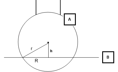
Remember that the calculation is done at the intersection of the probe sphere with the workplane or projection plane. If the probe sphere is too high (it doesn't intersect with the plane at all) or is too low (the hit is on the upper hemisphere or higher), PC-DMIS generates an error message to indicate that the feature has failed.

Side view of the workplane and the probe sphere
A - Probe sphere
B - workplane
h - height of the sphere center to the workplane
R - radius of the measured slot. The slot's width is twice this value.
r - radius of the probe sphere

If the probe sphere is so high that r is less than h, the intersection math fails, and PC-DMIS does not solve the slot. If the sphere center is below the workplane (B), PC-DMIS also does not solve the slot.