You can follow this topic to get started with your Romer Absolute arm with PC-DMIS. This procedure assumes you have a CAD model for your part.
Ensure that the base of the Romer Absolute arm is fixed in place.
Install the RomerRDS software. After you install RDS, the software displays a small red icon in your taskbar.
![]()
Physically connect the Romer Absolute arm to your computer. If your computer detects that the arm is ready for use, the red icon turns green.
![]()
For information on steps 1 -3, see "Step 1: Set Up the Romer Absolute Arm".
Start PC-DMIS.
From the Edit menu, choose Set Portable Interface and choose RomerRDS Arm.
Create a new measurement routine.
Choose File |Import to import a CAD model for your part.
Place your physical part on a sturdy, non-moveable, flat surface near the arm.
Orient the part so it more or less matches how it appears in the CAD model on the screen.
Fix your part in place so that it won't move when you probe it with the arm.
Select View | Other Windows | Status Window to show the Status window.
Select View | Other Windows | Quick Start to show the Quick Start interface.
From the Quick Start
interface, on the toolbar, click Alignments
( )
and then select SIX POINTS BEST FIT (
)
and then select SIX POINTS BEST FIT ( ).
).
From the QuickMeasure
or Graphic Modes toolbar, choose Program
Mode ( ).
).
Define the six points for the alignment on the CAD model:
On the top face, click three points spread out.
On the front face, click two points from left to right in a rough line.
On the left face, click a final point and click Finish to accept the alignment features.
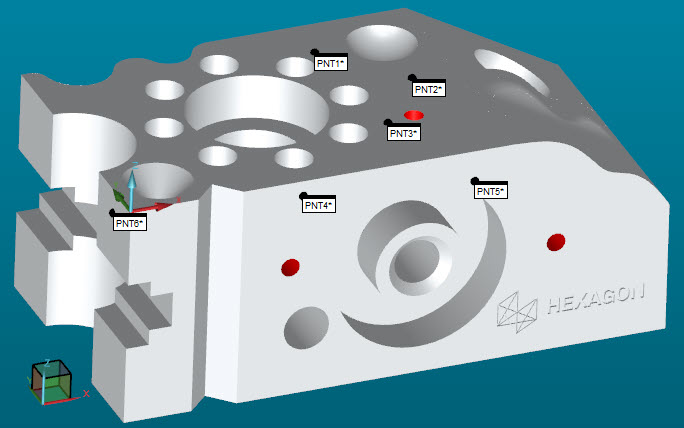
Sample Part with Six Points
Click File | Execute to measure the six points with your arm. If the software prompts you to load a probe, click OK.
From the Execution dialog box, follow the instructions below to take the alignment hits:
Because you physically contact the probe against the part to probe the points, the process of probing the part is often referred to as "taking a hit".
Use the arm to place the ball of the probe on the top surface of the part in position to take hits. Ensure that the probe points to the surface you want to measure.
Tilt the probe so that it is at an angle that is less than 90 degrees to the surface. This helps PC-DMIS find the surface.

Example of angle at 90 degrees (A) and a probe tilted to less than 90 degrees (B)
The next step directs you take hits with the probe for the alignment.
You take hits with the middle button (Take Hit) on the arm.
If you make a mistake, you can press the right button to remove it (Delete Hit).
You press the left button (Done) to accept the hit or hits.
Measure these hits with your arm. After each hit, press the left button (Done) to accept the hit:
Take three hits on the top surface (Z+).
Take two hits from left to right on the front surface (Y-).
Take the final hit on the left surface (X-).
Until you measure these alignment points, the probe representation in the Graphics window is not close to the CAD model on the screen when you take the hits.
You now have a functioning alignment.
Test the alignment:
On the arm, press and hold the cancel button (right button) twice. The first time you hold the button, PC-DMIS shows the Probe Readouts window. The second time you hold it down, the Probe Readouts window shows the T value. The T value shows the distance of the current probe's position to the part.
Whenever the probe touches the part, the T value should be close to zero.
Move the probe around the part and look at the T value in the Probe Readouts window. If the T value is close to zero all over the part, you know your alignment is good.

Example T Value - The distance (T value) decreases as the probe approaches one of the surfaces
From the Probe Mode
toolbar, choose Find Nominals from CAD Mode
( ).
This highlights the CAD element closest to the probe. When you probe
hits, it uses the nominal value from the CAD model for each hit you
take.
).
This highlights the CAD element closest to the probe. When you probe
hits, it uses the nominal value from the CAD model for each hit you
take.
Define any features you want to verify:
If you have a CAD, use QuickFeatures. To do this, press Shift (or Ctrl + Shift for points), and with your pointer, click on the feature in the CAD model. This adds that feature into the measurement routine. For information, see "Creating QuickFeatures" in the Core documentation.
If you do not have a CAD model, from the toolbar on the Quick Start interface, click Measure, and then choose the feature to measure.
Take the suggested number of hits to measure the feature and add it to the measurement routine.
Add dimensions you want to test:
From the Quick
Start interface, on the toolbar, click Dimension
( ).
).
Select the dimension you want to test.
Follow the on-screen instructions to add the dimensions. For information, see "Quick Start: Dimension Toolbar" in the Core documentation.