Turn the "F" axis to the limit, then
Turn the "E" axis 90 degrees.
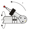
The two modes for a three-button configuration used on the RA7 and RA8 arms are discussed below.
To switch between Measure and Mouse modes,
Turn the "F" axis to the limit, then
Turn the "E" axis 90 degrees.
Measure Mode
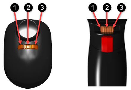
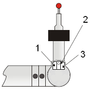
Romer Absolute Arm 6-axis (left) and 7-axis (right) button configurations
The following Measure mode functions are available for the buttons indicated above:
Desired Action |
Arm Procedure to Follow |
Click Done, OK, Yes, Finish, Next, or Create on a dialog box |
Press button 1 for less than one second. |
Erase the last hit or scan pass from the hit buffer. |
Press and hold button 1 for more than one second. When you use the Hexagon Absolute Portable Arm with the integrated laser scanner, you can delete the last scan pass using button 1 (the arm left button). |
Click Cancel, No, or Previous buttons on a dialog box |
Press and hold button 1 for more than one second. |
Bring up the Readouts window (DRO) |
Press and hold button 1 for more than one second when there are no hits in the hit buffer. |
Toggle the display of information in the Readouts window (DRO) |
With the DRO already open, press button 1 for less than one second. PC-DMIS shows the T value with the XYZ values in the DRO: XYZT |
Take a point |
Press button 2 for less than one second without moving the arm. |
Take a "Pulled Hit" |
Press and hold button 2 while pulling back on the arm, and then release the button within one second. For details, see "Using Pulled Hits for Probe Compensation". |
Scan |
Press and hold button 2 for more than one second while dragging the probe along the part's surface. |
Select features on the part using the arm |
Position the probe near the feature, press and hold button 1 and then press button 2. |
Mouse Mode
The following Mouse Mode functions are available for the buttons indicated above:
Desired Action |
Arm Procedure to Follow |
Use the left mouse button |
Press button 1. |
Use the right mouse button |
Press button 2. |
Use the middle mouse button |
Press button 3. |
Zoom out of the current CAD view |
Press button 1 (left mouse click) above the imaginary center line of the current CAD view. The further above the center line, the larger the zoom. |
Zoom in on the current CAD view |
Press button 1 (left mouse click) below the imaginary center line of the current CAD view. The further below the center line, the larger the zoom. |
Pan the view |
Press and hold button 1 on the CAD model while dragging the arm. |
Create a Point Info or Dimension Info box on the CAD view |
Press button 1 twice (double click) on a feature label. |
Rotate the CAD view |
Press and hold button 3 while dragging. |
Box Zoom |
Press and hold button 1, press and hold button 2, and drag a box on the part model. Release the buttons to zoom in on the selected portion. |