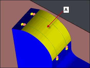
The options in the CAD selection group display the CAD coordinates for a Contour feature and enable you to perform CAD-related functions.
For a Contour feature, the coordinates are one or more CAD points that define the section cut plane, start point, and end point of the profile in which the contour points lie.
For example:

A. Single click on a selection point on the curved surface
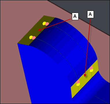
A. Multi-click on the selection points on the two planar surfaces
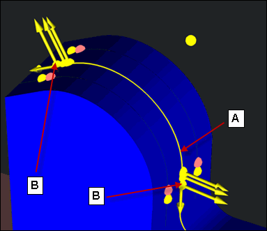
A. Section cut plane
B. CAD points that appear in the CAD selection area
Examples of the CAD Selection Point
When you select a CAD selection point for a Contour feature, you must click near a boundary. The selection point is projected on the boundary, and it gives the direction of the slice. For example:
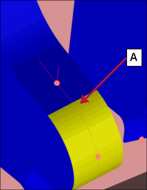
A. Correct CAD selection point
Do not click in the middle of a surface. In this case, the result fails. For example:
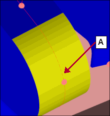
A. Incorrect CAD selection point
You can see the selected surface and therefore the corresponding boundaries when you hold down the Shift key, position your mouse pointer over the CAD drawing, and then click close to a border or boundary line.
Feature Options
The following graphics show the options for each feature.
BA and BD features:
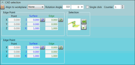
CAD selection group for BA and BD features
BF, BH, and BK features:
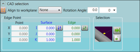
CAD selection group for BF, BH, and BK features
BM and BN features:
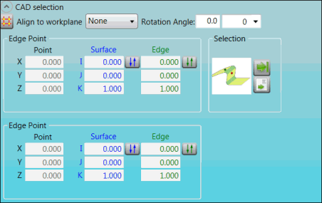
CAD selection group for BM and BN features
BP feature:
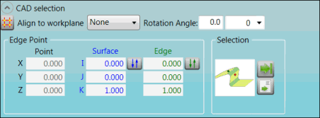
CAD selection group for BP feature
Descriptions
The following table describes the options.
For descriptions of the icons that appear in this group, see "Using the Icons".
| Item | Description |
Rotation Angle box |
Type the rotation angle of the section cut plane. |
Drop-down list |
Type or select the CAD cut-off distance from the click point. A value of "0" indicates that the distance is unlimited. |
Single click check box |
To enable single-click CAD selection, click this check box. To enable multi-click CAD selection and display the Counter list, clear the check box. |
Counter list |
Select the number of ESF features of this type in the measurement routine. |
Align to workplane list |
Select the workplane. |
Edge Point area |
X, Y, and Z Point boxes: These boxes display the X, Y, and Z nominals for the feature's location. I, J, and K Surface boxes: These boxes display the feature's surface locations. Edge boxes: These boxes display the calculated approach direction (vector) for the edge hit or for the points. |
Selection area
|
This image displays the navigation for the single-click or multi-click CAD selection. |
Selection area
|
This image displays the navigation path. |
More: