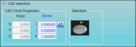
The options in the CAD selection group display the CAD coordinates for a Hole feature and enable you to perform CAD-related functions.
Feature Options
The following graphics show the options for each feature.
CD and CK features:

CAD selection group for CD and CK features
DI and DK features:
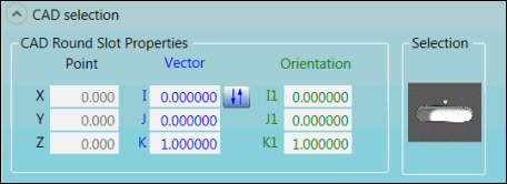
CAD selection group for DI and DK features
EI and EK features:
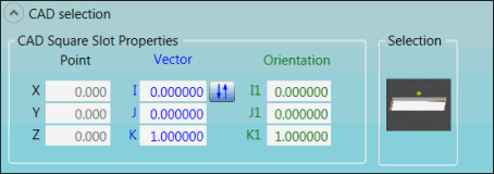
CAD selection group for EI and EK features
GD and GK features:
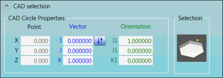
CAD selection group for GD and GK features
HD and HK features:
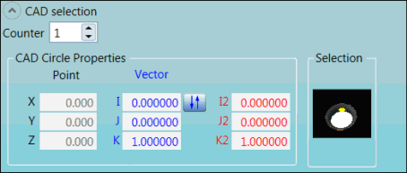
CAD selection group for HD and HK features
II and IK features:
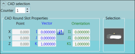
CAD selection group for II and IK features
Descriptions
The following table describes the options.
For descriptions of the icons that appear in the CAD selection group, see "Using the Icons".
Item |
Description |
Counter list |
Select the number of ESF features of this type in the measurement routine. |
CAD Circle Properties, CAD Square Slot Properties, and CAD Round Slot Properties areas |
X, Y, and Z Point: These boxes display the calculated point locations on the CAD model. I, J, and K Vector: These boxes display the calculated vector locations on the CAD model. I1, J1, and K1 Orientation: These boxes display the calculated angle locations on the CAD model. |
Selection area |
This image appears when PC-DMIS is in Surface mode. This mode makes a solid model's surfaces selectable when you click on the CAD data in the Graphic Display window. This image displays the navigation path. |
Selection area
|
This image appears when PC-DMIS is in Curve mode. This mode makes a wireframe's model of curves and lines selectable when you click on the CAD data in the Graphic Display window. This image displays the navigation path. |
For more information about Surface mode and Curve mode, refer to "Switching Between Curve and Surface Modes" in the "Editing the CAD Display" chapter in the PC-DMIS Core documentation.
More: