This calibration procedure allows you to determine the probe offset for your vision probe. PC-DMIS Vision also allows you to calibrate multi-sensor configurations with different probe tip types. For example, a vision probe and Contact probe are measured against the same tool or tools to establish a common offset frame of reference. The calibrated offset values for each tip are cross-referenced in relation to a common tool, such as a ring gage or sphere. See the "Relationship of Tips and Tools" topic for more information.
Calibrating tip types (be they all contact or a mix of contact, vision, and laser) against a common tool or standard allows measurements taken with one tip to be used with measurements taken by a different tip.
When Probe Offset Calibration is Used
Probe calibration is used at these times:
When you have multiple probes on your measuring system
When you have a video probe with different magnifications (such as 1X and 2X lenses or dual virtual cameras)
It does not matter which probe type you calibrate first. However, on a CMM, you would usually calibrate the Touch Probe first and on a vision Multi Sensor machine, you would calibrate the Optical Probe first. During calibration of the second probe, you must answer No to the question, "Has the qualification tool been moved or has the Machine Zero point changed?".
Once the tool position on stage is known and the probe tip offset has been calibrated once from the Probe Utilities dialog box, an AutoCalibrate Active Probe step can be added in the measurement routine to calibrate the probe offset as part of a measurement routine. As with a contact probe, the AutoCalibrate execution for a vision probe is based on the specified parameter set.
For more information on vision probes, see the "A Note on Probe Definitions" and "Considerations for vision probes" topics.
Probe tip offset calibration has been expanded to support calibrating the contact probe and vision probe offset using a sphere or ring tool. The usage follows the general rules for tip offset and diameter calibration.
Before you begin vision probe calibration, be sure to calibrate the optical center (if a zoom cell), field of view, and illumination for your vision probe. In this example, a ring tool is used for measurement.
Calibrating the Vision Probe Offset
CWS sensors do not have a tab option on the Setup Options dialog box. For details on calibrating probe offsets for CWS sensors, see "Step 4: Calibrate the Laser Probe" in the PC-DMIS Laser documentation.
Identify a Z measurement point of the face of the ring. The position of this point is defined in machine coordinates and is relative to the top center of the ring gage bore. This can be done using the "Probe Toolbox: Gage tab". These values are used when adding a ring tool.
On the Calibrate Probe dialog box, from the drop-down list, select Calibrate Probe Offset.
Select the needed tool from the List of Available Tools or click Add to define a new tool.
In this example, you can specify a 20 mm ring tool with the following values:
Tool ID: 20mm Ring
Tool Type: RING
Diameter: 20
Z Point Offset X: 15
Z Point Offset Y: 0
Z Point Offset Z: 0
Datum Depth Start: 1 (to accommodate the chamfer on the ring bore)
Datum Depth End: 14
Focus Offset: -0.5 (provides distance in Z from the top surface to the bore circle focus height)
Click Calibrate to open the Calibrate Probe Offset dialog box.
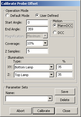
Calibrate Probe Offset dialog box
Set the following parameters as needed:
Operation Mode - Default Mode uses the default values. User Defined lets you alter the values.
Motion - Man+DCC mode requires that three manual points be taken at the start of the sequence whether or not you indicate that the tool position has changed. The remaining points will be taken automatically. DCC mode takes all points automatically unless you indicate that the tool has moved.
Start Angle - Angle in degrees in a Cartesian coordinate system as seen when looking down or –Z. A start angle of zero would be aligned to the +X. A start angle of 90 would be aligned to the +Y axis. The default value is 0.
End Angle - Angle in degrees in a Cartesian coordinate system as seen when looking down or –Z. An end angle of zero would be aligned to the +X. An end angle of 90 would be aligned to the +Y axis. The default value is 359.
The start angle and end angle specified here are different than the angle used for the contact probe and a sphere tool, which relates to the angle from the sphere equator to the pole.
Magnification - This option allows you to set the magnification to the "Maximum" setting or use the <Current> magnification. To ensure the highest accuracy, you should use the "Maximum" magnification to calibrate the vision probe offset. "Maximum" is the default setting.
Coverage - This percentage defines what portion of the zone is included for measurement. The default is 10%.
The start angle, end angle, and coverage percentage together define the location and size of the vision measurement targets around the circle. For larger circle sizes and higher optical magnifications, significant speed improvement can be achieved by reducing the coverage percentage. See the "Sample vision Circle Targets for Calibrate Probe Offset Parameters" topic.
Z Samples - This value is the number of Z samples that are taken to compute the Z position. The default is 5.
Illumination XY - This value indicates which illumination source to use for the XY measurements. Normally, bottom or sub-stage illumination is used for ring gage bore edge. This value can also be set to <Current> to use the current illumination settings.
Illumination Z - This value indicates which illumination source to use for the Z measurements. Normally, top or ring illumination is used for ring gage surface. This value can also be set to <Current> to use the current illumination settings.
Using <Current> for either of the illumination settings includes whether bulbs are on or off for Ring lamps.
If you find illumination settings that work well for calibration, create an illumination Quick Set so that these settings can be quickly recalled.
Parameter Sets - This area allows you to create, save, and use saved sets for your vision probe. This information is saved as part of the probe file and includes the settings for your vision probe. This parameter set can be retrieved for later calibrations, including the auto-calibration measurement routine feature.
To create your own named parameter sets:
On the Calibrate Probe Offset dialog box, modify any parameters.
From the Parameter Sets area, type a name for the new parameter set in the Name box, and click Save. PC-DMIS displays a message informing you that it created the new parameter set. To delete a saved parameter set, select it, and click Delete.
Click Calibrate. A message asks if the qualification tool has been moved or the machine zero point changed:
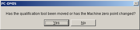
If PC-DMIS has not measured the actual tool location on the stage, select Yes.
If the tool has already been measured with a different probe type, select No.
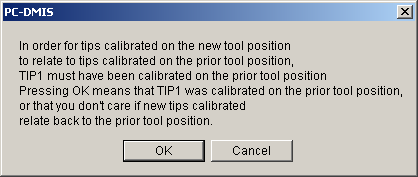
Click OK on the reminder that the tip must be calibrated.
If the tool has moved or Man+DCC motion is selected, take the three manual crosshair points evenly around the top of the datum bore circle. Adjust the stage position, including focus, as needed. The remainder of the calibration sequence executes automatically. It focuses on the bore top edge, measures the bore circle, moves to the Z focus offset relative to the bore, and does the Z position focus measurements. The probe tip offset data is updated with the measured offset based on the ring tool measurement. If you confirmed that the tools was moved, this measurement determines the XYZ location of the tool on the stage.
More:
Sample Vision Circle Targets for Calibrate Probe Offset Parameters