To create a surface scan using the Surface Topography sensor:
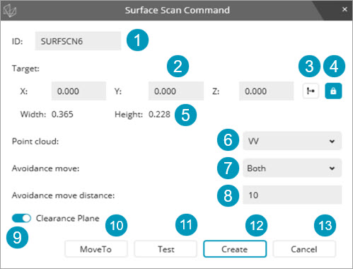
Enter a feature ID.
Define the XYZ position for the surface scan. You can do this in one of these ways:
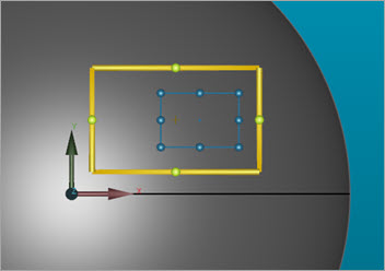
Click on the CAD model in the Graphic Display window. The X, Y, and Z boxes dynamically update based on the selected location on the CAD model.
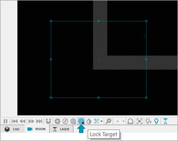
Click on the image in the Live View tab.
Type in the entries directly into the appropriate boxes.
Click the Read button to read in a position from the machine.
Click the  Lock
Target button to lock and unlock the target
position. PC-DMIS sets this option to lock by default when you are
in Edit mode.
Lock
Target button to lock and unlock the target
position. PC-DMIS sets this option to lock by default when you are
in Edit mode.
The Width and Height values are read-only and show the target's width and height.
Select a pointcloud from the list or create a new pointcloud. For details on how to create a pointcloud, see the "Using Pointclouds" topic in the PC-DMIS Laser documentation.
Select an Avoidance move option from the list. The available options are:
None
Both
Before
After
Type the Avoidance move distance in this box.
Click the Clearance Plane button to enable or disable this function.
Click the Move To button to move the machine to the XYZ coordinates of the surface scan. DCC is required for this step.
Click the Test button to perform a test run of the surface scan with the current settings. DCC is required for this step.
When you are satisfied with the setup, click the Create button to create the Surface Scan command in the Edit window.
Click the Cancel button to close the Surface Scan Command dialog box.
Notes on Surface Scans Using the Surface Topography Sensor
When you click the Test button on the Surface Scan Command dialog box, PC-DMIS stores the measured data in a temporary pointcloud.
When you edit an existing surface scan, the software transfers the data from the pointcloud to an internal pointcloud. If PC-DMIS detects changes to any parameter related to the measurement, it purges the existing pointcloud data.
PC-DMIS displays the measured data in the pointcloud in the Graphic Display window.
When you click the Create button, PC-DMIS transfers the data to the pointcloud referenced in the Surface Scan Command dialog box.
Multiple surface scans commands can reference the same pointcloud ID.
More:
Surface Topography Illumination Settings and Measurement Strategy