Illumination Settings
You can define the illumination settings from the Probe Toolbox or the Live View Overlay. To do this, use the slider on the Illumination tab or the Live View Overlay as needed.
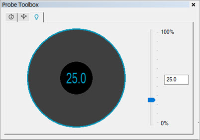
Illumination tab of the Probe Toolbox for the Surface Topography sensor
You can also adjust the Illumination settings from the Live View toolbar. For details on the Live View controls, which include descriptions of the toolbar options, see "Live View Controls".
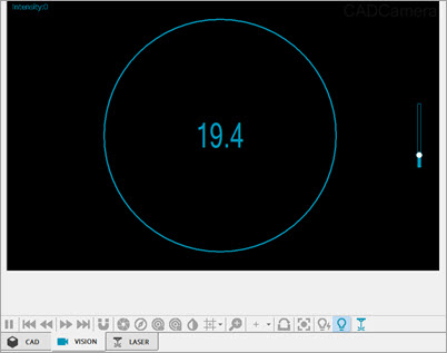
Illumination Overlay in Vision Live View for the Surface Topography sensor
Define the Topography Sensor
To define the Topography sensor in PC-DMIS:
Open the Probe Utilities dialog box (Insert | Hardware | Probe) and select your Topography sensor from the Probe file list. For details on how to define your sensor, see the "Defining Probes" section in the PC-DMIS Core documentation.

Probe Utilities dialog box - Topography sensor probe file selected
After you select the Topography sensor file or build it from the Probe description area, click the Edit button.
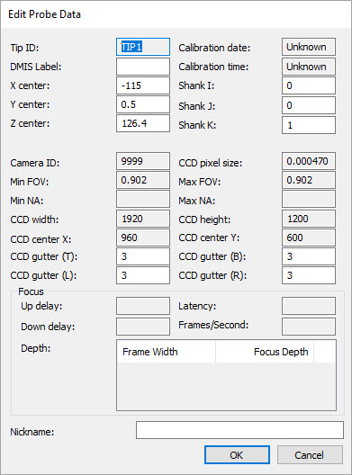
Edit Probe Data dialog box for the Topography sensor
Review the settings to make sure they are correct. For details on this dialog box, see the "Edit Probe Data" section of the PC-DMIS Core documentation. Click OK to exit and save your changes or click Cancel to close the dialog box without saving.
Measurement Strategy
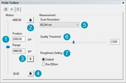
Measurement Strategy tab of the Probe Toolbox for the Surface Topography sensor
To setup the measurement strategy for the Surface Topography sensor:
Select the Measurement Strategy tab on the Probe Toolbox.
Adjust the Drive Position slider (1) to position the Micro Drive.
Click the Upper Bound button (2) to lock and unlock the upper bound position of the Micro Drive.
Click the Center Scan Position button (3) to adjust the center position of the scan range.
Click the Lower Bound button (4) to lock and unlock the lower bound position of the Micro Drive.
From the Drive Scan Resolution list (5), select the appropriate Micro Drive scan resolution option.
Adjust the Quality Threshold slider or enter the value directly into the box (6) to determine the points PC-DMIS filters from the scan. The software only filters out points which have a quality tag below this value.
Select a Roughness Setting from the options (7). Use the Default option for roughness measurements with an unknown Ra.
More: