If your probe (camera) type has not yet been defined, use the Probe Utilities dialog box to create a probe file.
To create a new probe file for your vision probe, follow these steps:
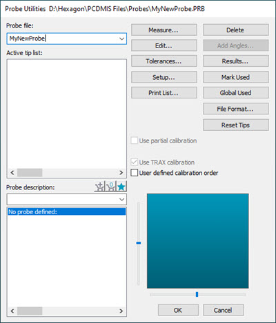
Select the Insert | Hardware Definition | Probe menu option. The Probe Utilities dialog box appears. (This dialog box automatically appears whenever you create a new measurement routine.)
Probe Utilities dialog box
Type a Probe File name that best describes your vision probe.
Highlight the No probe defined option in the Probe description area of the Probe Utilities dialog box.
Select the appropriate probe from the Probe description list.
For each "empty connections", select the remaining components in the same manner until you complete the probe definition. The defined tip displays in the Active Tip List when completed.
Notice that PC-DMIS does not show the image of the probe. This is usually desirable so that it does not obstruct the view of the part as you perform measurements. However, you can double-click the probe component in the Probe description area of the Probe Utilities dialog box to open the Edit Probe Component dialog box and then select the Draw this component check box.
For additional information on how to define probes, see the "Defining Hardware" chapter in the PC-DMIS Core documentation.