Step 5: Measure Datums B and C
In this step, the software measures the for Datums B and
C. Based on the intersection of the two lines,
a is also constructed
to establish the XY origin.
To measure Datum B:
Select the Magnification
tab  , and adjust
the magnification to about 25% of maximum. The actual magnification
value varies based on your lens.
, and adjust
the magnification to about 25% of maximum. The actual magnification
value varies based on your lens.
Select the Illumination
tab  , and set
the Top Light to 0% (Off). Set the Bottom Light to 35%.
, and set
the Top Light to 0% (Off). Set the Bottom Light to 35%.
Select the CAD tab.
From the Graphic Modes
toolbar, if it's needed, select Scale-To-Fit
( ).
).
From the Graphic Modes
toolbar, select the Curve Mode button ( ).
).
From the Auto Feature
toolbar, click the Line button ( ) to open the Auto Feature
(line) dialog box.
) to open the Auto Feature
(line) dialog box.
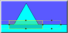
Click a
for the left anchor point of the line and on the front edge towards
the left end.
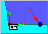
Click a
for the right anchor point of the line and just to the left of the
slot (to the right of the upside-down "V" as show in the
image below). The software displays the target.
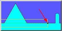
Since the line stretches across
a void (the upside-down "V"), this region must be excluded so
no points are taken in that segment.
Right-click inside the rectangular target.
From the popup menu, select Insert Hit Target.
This divides the single rectangular target into two targets.
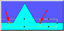
Repeat the above step to insert a third target.
Drag the two target dividers so that one is
on each side of the upside-down "V".
Select the Vision
tab.
Position the camera over the part.
From the Illumination
tab , adjust
the Top Light to a value that makes the
surface visible but not too bright. Move Z to focus as necessary.
Select the Hit Targets
tab  . Notice
three targets are shown: EA1, EA2, and EA3. You should not use the
second target (EA2) that crosses the void. Double-click on Normal
in the EA2 density field and select None.
. Notice
three targets are shown: EA1, EA2, and EA3. You should not use the
second target (EA2) that crosses the void. Double-click on Normal
in the EA2 density field and select None.
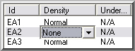
Notice that the EA2 target
segment shows hash lines to indicate the area where no data will be taken.
From the Auto Feature
dialog box, rename the default Line Auto feature name to DATUM
B.
Click Create and
then Close.
To measure Datum
C:
From the Auto Feature
toolbar, select the Line button () to open the Auto Feature
(line) dialog box.
If you want to reset the number
of targets to 1, close and then reopen the Auto Feature
dialog box.
Click two points
on the left edge (one in the front and one in the rear).
Change the default name to DATUM
C.
Click Create to add
this line to the measurement routine.
Click Close to exit
the Auto Feature dialog box.
To construct a point from
the intersection of the lines:
Select the Insert | Feature
| Constructed | Point menu item or Constructed
Point ( )
from the Constructed Features toolbar (View | Toolbars | Constructed Features). The Construct Point dialog box appears.
)
from the Constructed Features toolbar (View | Toolbars | Constructed Features). The Construct Point dialog box appears.
Select the  Intersection option.
From the feature list, select DATUM
B and DATUM C.
Change the ID to FRNT LEFT
CORNER, click Create, and then click
Close.
The datum features are now created.
Next Step ...