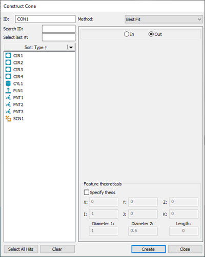
Construct Cone dialog box
PC-DMIS allows several methods for constructing a cone. The following table lists the various types of constructed cones, along with their necessary inputs. Some features may require no inputs while others may require six inputs or more. The term "Any" in the table below indicates that the construction can take any type of feature as input for construction. PC-DMIS allows you to select the features in any order.
CONSTRUCT FEATURE TYPE |
SYMBOL IN EDIT WINDOW |
# OF INPUT FEATURES |
FEATURE #1: |
FEATURE #2: |
COMMENTS |
Auto Cone |
- |
- |
- |
- |
See "Auto Cone Construction". |
Best Fit Cone |
BF |
At least 6 inputs are needed. |
- |
- |
Constructs a best fit cone using the given inputs. See the Note below for recommended inputs. |
Best Fit with Recomp Cone |
BFRE |
At least 6 inputs are needed. (1 must be a point) |
- |
- |
Constructs a best fit cone using the given inputs. See the Note below for recommended inputs. |
Cast Cone |
CAST |
1 |
Any |
- |
Constructs a cone at the centroid of the input feature. |
Project Cone |
PROJ |
1 or 2 |
Any |
Plane |
Using one input feature, projects the cone to the workplane. |
Reverse Cone |
REV |
1 |
Cone |
- |
Constructs a cone with a reversed vector for the axis. |
Extracted Cone |
EXTRACTED_CONE |
1 |
COP or Mesh |
- |
Constructs an extracted cone from the COP or Mesh object at the specified diameter or height of the cone. |
For Best Fit (BF) or Best Fit Recompensate (BFRE) constructions, while you can use any feature type for your input features, BF and BFRE fit types are typically used with point features or point sets (a scan of points, a feature set with points, or an expression that resolves to an array of points).
If you select inappropriate feature types, PC-DMIS displays this message on the Status bar:
"Cannot construct [feature]. Combination of input features not accepted."
To construct a cone:
Open the Construct Cone dialog box (Insert | Feature | Constructed | Cone).
From the Method list, select the method of the constructed cone. The available options are:
Auto Cone
Best Fit
Best Fit Recompensate Cone
Projected Cone
Cast Cone
Reversed direction Cone
Extracted Cone
If you select the Best Fit or the BF Recomp (Best Fit Recomp) method for this feature, PC-DMIS allows you to click the Select All Hits button to create the construction from the individual hits of the input features instead of their centroids.
To do this:
From the Feature list, select the feature or features that you want to use to create the constructed feature.
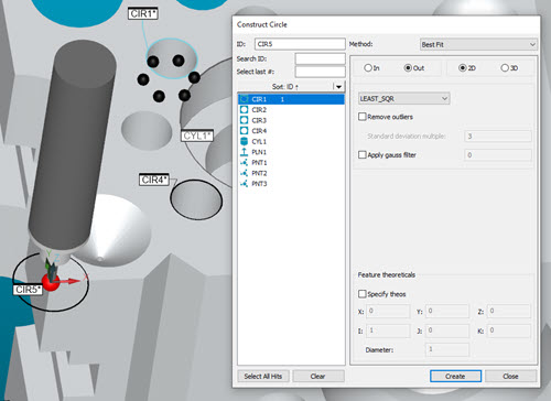
Example showing a selected feature prior to clicking the Select All Hits button
Click the Select All Hits button to display all the components that comprise the selected feature or features.
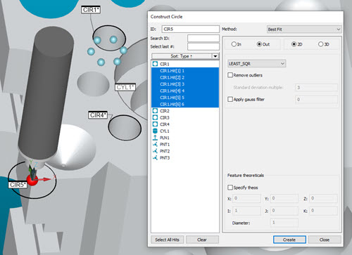
Display of items that make up the selected feature are highlighted in the dialog box and in the Graphic Display window
PC-DMIS displays and highlights all the components of the selected feature (or features) in the Feature list of the dialog box. You can select or de-select any of the features or feature components shown in the list to include or exclude them.
Click the Create button to create the Constructed feature based on the final features and feature components that you selected.
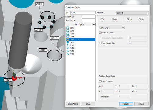
Constructed feature created based on selected items from the Feature list
Use the table above to select the features from the Feature list based on the selected method.
Select the In or Out option. For details, see the "In / Out Cone" topic in this documentation.
If you want to change the feature theoretical values, select the Feature theoreticals check box and type in the values. For details, see the "Specifying Feature Theoreticals" topic in the PC-DMIS Core documentation.
Click the Create button.
The Edit window command line for this option would
read:
feature_name=FEAT/CONE,TOG1,TOG4,ANG
THEO/x_cord,y_cord,z_cord,i_vec,j_vec,k_vec,ang
ACTL/x_cord,y_cord,z_cord,i_vec,j_vec,k_vec,ang
CONSTR/TOG2,TOG3,......
feature_name=FEAT/CONE,TOG1,TOG4,LENG
THEO/x_cord,y_cord,z_cor,i_vec,j_vec,k_vec,leng,diam_1,diam_2
ACTL/x_cord,y_cord,z_cor,i_vec,j_vec,k_vec,leng,diam_1,diam_2
CONSTR/TOG2,TOG3,......
The actual Edit report displays in all capital letters.
TOG1 = POLR or RECT
TOG2 = CONE
TOG3 = BF / BFRE / CAST / PROJ / REV
TOG4 = IN / OUT
TOG5 = ANG / LENG
The first three lines that display in the Edit window are similar for constructed cones. If the feature is bound or unbound, the theoretical and actual values that are displayed will vary. The fourth line will be slightly different, according to the type of feature you are constructing. You can switch between the different types of cones by placing the cursor on TOG and clicking the left mouse button. The keyboard can also be used to switch toggle fields. (See "Command Mode Keyboard Functions" in the "Using the Edit Window" chapter.)
When two or more features are involved, PC-DMIS automatically determines the necessary order of the input features. This improves the accuracy of the measurement process.
Auto is the default method for constructed cones. This option automatically determines the best way to construct a cone using the input feature(s). See "Auto Cone Construction"
The following paragraphs describe the available options for constructing a cone:
More:
Constructing a Best Fit or Best Fit Recompensate Cone
Changing the Direction of a Cone