You can use the ClearanceCube Settings window to define the ClearanceCube motion for each feature and tip in the measurement routine.

ClearanceCube Settings window
PC-DMIS displays the ClearanceCube Settings window automatically when you activate ClearanceCube for the measurement routine.
From the ClearanceCube toolbar, you can use the ClearanceCube Settings Window icon to show or hide this window. You can also open this window from the View | Other Windows | ClearanceCube Settings menu option.
You can dock the ClearanceCube Settings window at the top or bottom of the Graphic Display window. To float the ClearanceCube Settings window, press the Ctrl button and then click and drag the window to the desired location.
ID(s) - This list displays one or more feature IDs based on your selection of features in the Edit window. To do this, follow these steps:
Place your cursor on a feature in Command mode or select a feature in Summary mode to display or edit the settings for the ClearanceCube.
To edit the the ClearanceCube settings for more than one feature at the same time, select them in the Edit window and then make the necessary changes.
From the ID(s) list, select Features or Tips. This box appears when you select multiple features and tips in the Edit window.
Based on your selection from the ID(s) list, the list shows the features or tips. Select the item in the list for configuration.
If you position your mouse cursor over a command in Command mode or select a command in Summary mode that does not require ClearanceCube settings, PC-DMIS displays the message “ClearanceCube is not required for the selected commands”.
Activate ClearanceCube Moves - This switch determines whether you want to use ClearanceCube motion for the features you selected in the ID(s) list.
Starting Face - This determines the ClearanceCube face that PC-DMIS moves to before it measures the feature. You have these options:
Select a face
Use Tip Vector
Set the Starting Face to OFF if you only want the ending motion to occur for the feature.
Ending Face - This determines the ClearanceCube face that PC-DMIS moves to after it measures the feature. You have these options:
Select a face
Use Tip Vector
Set the Ending Face to OFF if you only want the starting motion to occur for the feature.
The feature vector determines the default setting for the ClearanceCube Starting Face and Ending Face options. PC-DMIS marks the ClearanceCube uses Tip Vector for Start/End Face check box in the General tab of the Setup Options dialog box (Edit | Preferences | Setup) by default. It is recommended to use the tip vector.
Based on constraints set in the Constraints tab, the selection of some axes for the starting and ending faces may not be available.
For Tip Commands
From the ID(s) list, select the features or tips. This box appears only when you select multiple features and tips in the Edit window.

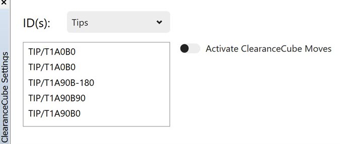
ClearanceCube Settings Window for Tips
When you select the Tips option from the ID(s) list, the ClearanceCube Setting window only shows the Activate ClearanceCube Moves setting.
The ClearanceCube Shortcut Menu
In addition to the ClearanceCube Settings dialog box, PC-DMIS provides a right-click menu. To access this menu, follow these steps:
If you are in Command mode, place your cursor on a feature. If you are in Summary mode, click a feature to select it.
Right-click the feature and select the Path | ClearanceCube option.
From the Starting Face and Ending Face list, select the face to align the ClearanceCube to. The available options are -X, +X, -Y, +Y, -Z, +Z, Use Tip Vector, and Off.