In this Topic Hide
For common datums, PC-DMIS allows you to mix the same feature types. You can combine individual features with a pattern or multiple patterns. PC-DMIS only allows you to mix different feature types in these cases:
| # of Input Features | Common Datum Feature #1 | Common Datum Feature #2 | Common Datum Features #3-5 (When Selected) | Comments |
| Minimum of two features | Plane | Plane | Plane | Only multiple parallel planes. See Example 1. |
| 2 | Cylinder | - | Only a single Plane & single Cylinder that is perpendicular to the plane. See Example #6. | |
| 2 | Cylinder | Cone | - | Only a single Co-axial Cone and Cylinder. See Example #7. |
| 2 | Plane | - | Only a single Plane and single Cylinder that is perpendicular to the plane. See Example #6. | |
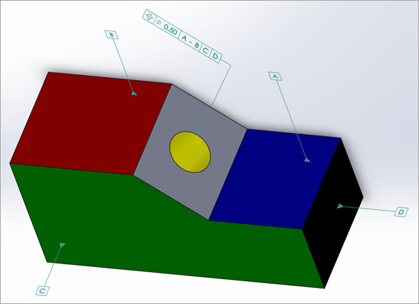
| Minimum of two features | Circle | Circle or Cylinder | Only Co-axial Circles and Cylinders. See Example #8. | |
| Minimum of two features | Cylinder or Pattern of Cylinders | Cylinder or Pattern of Cylinders | Each feature or pattern can be internal or external features of size and have different nominal sizes. See Examples #2, 4, and 5. | |
| Minimum of two features | Pattern of Cylinders | Cylinder or Pattern of Cylinders | Cylinder or Pattern of Cylinders | |
| Minimum of two features | Circle | Circle or Cylinder | Circle or Cylinder | Only Co-axial Circles and Cylinders. See Example #8. |
| 2 | Cone | Cylinder | - | Only a single Co-axial Cone and Cylinder. See Example #7. |
| Minimum of two features | Sphere | Sphere or Pattern of Spheres | Sphere or Pattern of Spheres | Each feature or pattern must be internal or external spheres and have the same nominal size. |
| Pattern of Spheres | Sphere or Pattern of Spheres | Sphere or Pattern of Spheres | ||
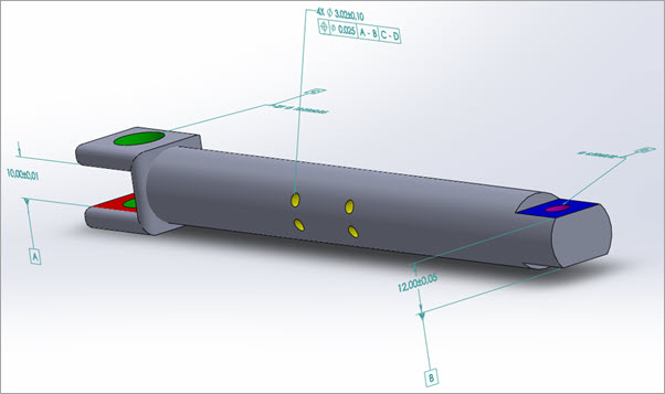
| Minimum of two features | 3D Width | 3D Width or Pattern of 3D Widths | 3D Width or Pattern of 3D Widths | Each feature or pattern can be internal
or external features of size and have different nominal sizes.
See Example #3.
When you select multiple widths (or a pattern of widths), they need a common workplane direction to be an acceptable datum. The workplane direction is necessary to simulate the Datum Reference Frame (DRF), similar to a functional gage sliding into various widths.
|
| Pattern of 3D Widths | 3D Width or Pattern of 3D Widths | 3D Width or Pattern of 3D Widths |
Any unsupported combination of features results in an error message when you attempt to create the Feature Control Frame (FCF), such as:
PC-DMIS
Multi-feature datum error. This may be caused by incorrect nominals (x, y, z or i, j, k vector) or an unsupported combination of features.
When you select datum features as a common datum, ensure that they either all have surface data, or that they all do not have surface data.
If you must combine datum features with and without surface data, it is only supported with Material Condition Modifiers (M or L). The datum math is available, but it only applies to datum features with surface data. PC-DMIS does not recalculate datum features with no surface data because they use the math from the feature command that represents the datum.
When you create common datums in the Datum Definitions (DATDEF) dialog box, PC-DMIS only performs a limited error check. All validity checks are performed by the Geometric Tolerance command when the FCF is built.
Once the FCF is completely built, PC-DMIS performs the final verification that the common datum is supported. If the FCF verification fails, PC-DMIS indicates this failure with an error message.
If the common datum has an error, please refer to the above table and general guidelines regarding Common Datums in order to address and resolve any problems with the Common Datum.
PC-DMIS currently supports a maximum of five single datums or datum patterns combined to define a common datum (for example: A – B – C – D – E).
PC-DMIS does not support the mixing of datum features that have surface data with datum features that do not have surface data. For more information, see "Feature Types With and Without Surface Data".
As required by ASME Y14.5 and ISO 5459, the common datum simulators for the pattern are nominally oriented and located with respect to each other. PC-DMIS supports the use of a modifier (MMB or LMB) on the common datum, when ALL the features (within the common datum) are “features of size”. When any of the features are NOT a feature of size, modifiers are not allowed.
In order for PC-DMIS to correctly grow or shrink the simulator sizes simultaneously and correctly calculate the material boundaries (when using MMB or LMB), you must have first toleranced each datum to its higher precedence datums. Also, you must make sure to include their size tolerances before you allow any other geometric tolerances to reference those datums.
That is, the tolerances on the datum must be EARLIER in the measurement routine than the geometric tolerances that reference those datums.
Examples of supported common datum combinations are described in the examples below.
Example #1: Plane A (blue) and Parallel Plane B (red) as Common Datum A-B
Example #2: External Cylinder B (red) with a Pattern of External Cylinders C (blue) as Common Datum B-C
Example 3: External Width A (blue) with an External Width B (red) as Primary Common Datum A-B
Example 4: Internal Cylinder C (green) with an Internal Cylinder D (magenta) as Secondary Common Datum C-D
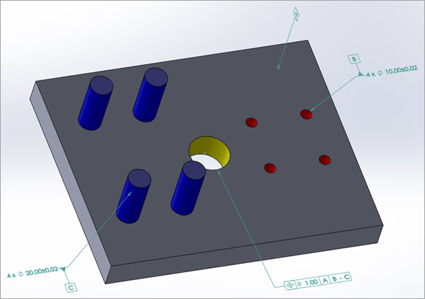
Example 5: Pattern of Internal Cylinders B (red) and Pattern of External Cylinders C (blue) as Common Datum B-C
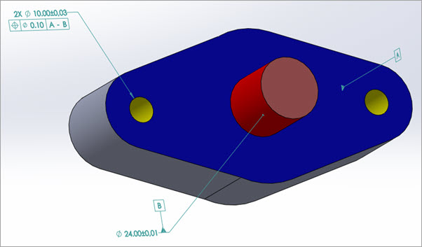
Example 6: Plane A (blue) and External Cylinder B (red) as Common Datum A-B
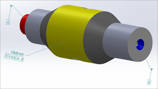
Example 7: External Cylinder A (red) and Coaxial Internal Cone B (blue) as Common Datum A-B
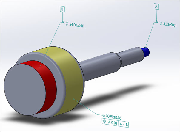
Example 8: External Cylinder A (blue) and Coaxial External Cylinder B (red) as Common Datum A-B
More: