In PC-DMIS, lock onto the laser scanner. (It is automatically set as the active probe in the Edit window.) When PC-DMIS shows the Scanning window, you are ready to begin scanning.
From the scanner's control panel, enter the scanner settings. If you use an LAS scanner, you can also double-click the LAS scanner button to advance to the next RDS scanning profile.
Optional:
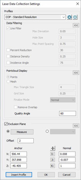
Select the Pointcloud Data Collection Parameters button
 from the Pointcloud or QuickCloud
toolbar (View | Toolbars).
from the Pointcloud or QuickCloud
toolbar (View | Toolbars).From the Exclusion Plane area, click the Measure button.
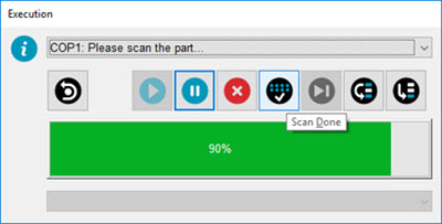
Scan the table surface and then click the appropriate button on the scanner when done.
In the exclusion plane Offset field, enter the offset value (for example: 1 for 1mm) and then click the check box to enable.
Click OK to close the Pointcloud Data Collection Parameters dialog box.
PC-DMIS supports many sensors including the AS1 and the AS1-XL sensors.
The AS1-XL sensor is capable of measuring with a much larger stand-off than other laser sensors so, it requires a different set of scanning parameters.
When PC-DMIS auto-detects that the AS1-XL sensor is the active sensor, it automatically switches the scan profile with the appropriate parameter settings required by the sensor. The profile name remains the same, but you can see that some of the parameter changes of the profile setting are visible in the Laser Data Collection Settings dialog box. Other changes are made in the background which are not exposed.
If you switch from an AS1-XL sensor to a different laser sensor, PC-DMIS auto-detects the change and updates the scan profile again with the applicable parameters.
For details on sensor profile settings, see the "Laser Data Collection Settings" section of the PC-DMIS Laser documentation.
For details on the Portable toolbars, see "Using the Portable Toolbars".
For details on the Laser Data Collection Settings dialog box, see "Laser Data Collection Settings" in the PC-DMIS Laser documentation.
Press and hold down the appropriate scanner button and scan the part.
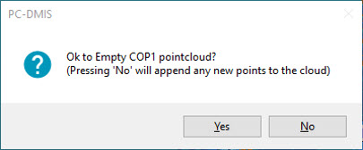
If a COP feature exists, the pointcloud data is added to the COP.
If a COP feature does not exist, a new COP is created (COP1) and populated with the pointcloud data.
If the scan beam is accidentally broken (for example, when changing faces), you can lock back onto the scanner and continue scanning.
When you complete the scan, you can lock onto a different probe (for example, a reflector or T-probe) to reconnect to the tracker. There is a 10-second delay when you disconnect from the scanner.
You can add pointcloud data to the COP at any time by locking onto the scanner and starting to scan.
 to re-execute the measurement routine.