PC-DMIS Blade is an analysis package that takes collected data (2D or 3D) about a measured airfoil and three-dimensionally analyzes and compares it against nominal data. You can display various characteristics in reports and plots. You can use these characteristics to identify problems and solutions to manufacturing and engineering issues.
You can use PC-DMIS Blade for:
Manufacturing: Process control (in-process inspection) and final acceptance
Engineering: Process engineering and reverse engineering
There are two ways that you can use PC-DMIS Blade to analyze an airfoil:
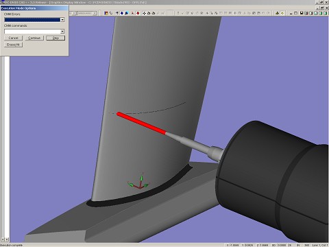
Execution Mode: You can use PC-DMIS to measure the blade on a CMM, for example. PC-DMIS creates a Blade Report (.rpt) file from the measurement results. PC-DMIS then opens the file in PC-DMIS Blade to analyze the measured airfoil sections and to generate the reports and plots. This is typically used in a manufacturing setting where the operation is automated and requires little operator input.

Measuring a blade
Investigation Mode: You can use this mode to analyze Blade Report (.rpt) files created by PC-DMIS. Open PC-DMIS Blade from your shortcut or from the Start menu to create a custom analysis of an airfoil. This mode is typically used in an engineering or reverse engineering scenario. For more information on how to create a plot in Offline mode, see "Creating Profile Plots".
The mean camber line (MCL) is a fundamental concept for all blade types and affects the majority of calculations, either implicitly or explicitly.