Blades have the concept of a "mean camber line" or MCL, which is a sort of center-line of the blade. It is a curved line halfway between the concave side and the convex side, and extrapolating it defines the leading edge point and trailing edge point. The MCL is used for several purposes in PC-DMIS Blade:
To define the leading edge point and trailing edge point
For certain types of bestfits
For several calculations, such as edge thickness and edge angle
Blade always computes an MCL for every section. A measured MCL and a nominal MCL are always associated with the measured curve and the nominal curve, respectively. A variety of calculations use the MCL either explicitly or implicitly. Many of the bestfits use the MCL as well. A few types of calculations additionally have a computation method named "MCL," which are named because of the way the computation method uses the MCL differently than the other computation methods. For details about the MCL computation method, see "MCL".
Blade has always had an MCL algorithm, which works fairly well in most cases. However, this old algorithm did not work well with some newer and more complex blade designs. Bumps, notches, and grooves can be problematic for the algorithm. Square-ended blades were handled specially in the old algorithm, but they still did not always perform perfectly.
Blade 6.0 introduced a new (optional) MCL algorithm, which has these improvements:
Robust math that always works regardless of the bumps, notches, or grooves that are on the blade
A way to ignore non-repeatable blade ends so that they do not affect the MCL
The MCL Algorithm Far from Blade Ends
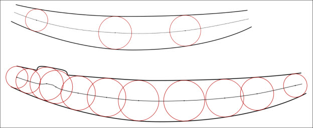
Far from the blade ends, both MCL algorithms inscribe circles between the convex and concave side and interpolates between the circle centers. With the new MCL algorithm, this also works for bumps and notches in the blade; the MCL gains a kink from the bump or notch, but it works just fine and is mathematically defined the way we expect it to be defined. This part of the algorithm has the same goals as the old algorithm; it just is more mathematically robust and so it can handle complex blade surfaces.
The new MCL algorithm is adaptive to the blade complexity: the number of circles it inscribes can vary from hundreds to thousands depending on how complex the blade surface is. Blade will inscribe more circles near bumps, kinks, notches, and so forth so the MCL can be accurate in those regions.
Following is an example:

MCL algorithm example
With the new MCL algorithm, the blade ends need to have section-by-section customization for how much of the blade ends are ignored. This is configured through the new CAMBER_OFFSETS in the Tolerance file (.tol). This new keyword specifies how much of the blade ends to ignore. It is followed by two numbers: a leading edge and a trailing edge camber offset. A camber offset is a distance from the edge, within which the nominal/measured curve is ignored. This new keyword is how Blade knows whether to use the new MCL algorithm: it only uses the new MCL algorithm on sections where this parameter is defined.
Because the camber offset can be defined differently for every section and has different values for the leading and trailing edges, it is a flexible way to selectively ignore parts of the leading and trailing edges. For the camber offset for each nominal curve, Blade takes the edge point defined in the Nominal file (.nom) and draws a line that is the camber-offset distance away from the Nominal file edge point, in the direction of the surface normal defined in the Nominal file. Everything between the edge point and the offset line is ignored for inscribing circles. For measured curves, the offset line is parallel to the nominal offset line, and the backoff distance is from the furthest point on the measured curve in that direction.
Example 1. Following is an example of camber-offset lines for a leading edge:
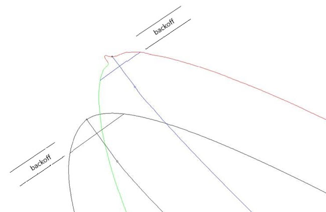
Example of camber-offset lines for a leading edge
This example shows a nominal curve, its MCL, and its camber-offset line. It also shows a measured curve, its MCL, and its camber-offset line. In addition:
The nominal camber-offset line is the CAMBER_OFFSETS distance away from the leading edge point defined in the Nominal file. The orientation and distance direction are defined by the surface normal in the Nominal file.
The offset line serves to cut off the tip of the blade as far as inscribing circles is concerned. The measured offset line is parallel to the nominal one, and it has the same camber offset distance.
The camber offset distance is relative to the furthest-away point on the measured curve, which is a small measured kink in this case.
The small circle is the last-inscribed circle that touches both the convex and concave sides in a tangent-parallel way.
Example 2. Following is an example of the MCL and the last-inscribed circle:
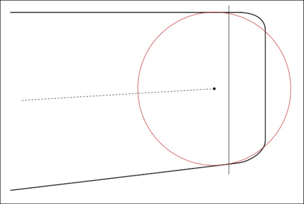
Example of MCL and last-inscribed circle
This example shows a rounded-square ended blade's trailing edge. In addition:
The camber-offset distance is large enough to cut off all of the rounded-square edge, which for this blade is not repeatable.
The last-inscribed circle is also shown.
The manner in which the last-inscribed circle always matches both curves in a tangent-matching way is also shown. This means that the circle typically contacts the concave or convex curve at the camber-offset line on only one side or the other, but not both.
For normal-ended blades, the camber offset is usually small. The offset only needs to be large enough to avoid any non-repeatable issues with the spline at the tip. For example:
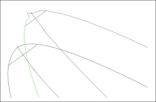
Example of camber offset for normal-ended blade
In this example, the measured curve has a kink near the leading edge, which may be a rough spot on the tip (although the probe compensation algorithm is probably exaggerating it). The camber offset has been set large enough to ignore that region of the curve so that it does not affect the MCL. For better-behaved measured normal-ended blade sections, the camber offset can be set even smaller. A typical camber offset on a very smooth blade might be one-tenth of the nominal edge radius. Some experimentation may be required, depending on the manufacturing and inspection processes; the goal is a camber offset that is large enough to avoid non-repeatable data at the edge but small enough to capture all of the repeatable data on the concave and convex sides.
As observed above, the raw MCL does not intersect the leading and trailing edges, but is instead farther in, based on the last-inscribed circle. The MCL is then linearly extrapolated past the last-inscribed circles until it intersects the edge curves (one on each edge).
In some cases, the measured surface may bend in the vicinity of the last-inscribed circle. This can make the extrapolation be a different direction than desired. Increasing the camber offset value can make the MCL ignore parts of the surface where the measured surface has a bend.
Some geometrical identities can clarify the extrapolation direction. For example:
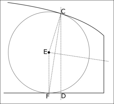
Example of extrapolation
This example shows a square-ended blade, zoomed into the end.
The camber-offset line is line CD.
The center of the last inscribed circle is E, which touches the surface at C and F.
Triangle CEF is always an isosceles triangle, and the extrapolation direction is always orthogonal to the base of the isosceles triangle.
Geometric Derivation of Tangent Directions of the MCL
The example above also applies to most inscribed circles and not just the last-inscribed circles. Most inscribed circles contact the surface at a total of two points: one for each side of the circle. The MCL at the given circle's center point is exactly orthogonal to the base of the isosceles triangle.
Some blades have a few inscribed circles that contact three points: two points on one side, and one point on the other side. At such points, the MCL is tangent-discontinuous; it is orthogonal to one of the isosceles triangle bases in one direction and orthogonal to the other isosceles triangle base in the other direction.
The new MCL algorithm is enabled by the CAMBER_OFFSETS parameter defined in the Tolerance file (.tol). It is enabled for every section for which the CAMBER_OFFSETS parameter is defined. It is disabled for every section that does not have a CAMBER_OFFSETS parameter; on those sections, the old MCL algorithm is used.
If CAMBER_OFFSETS is defined by default, the new MCL algorithm is used on every section. This parameter can be put directly (by hand) into the Tolerance file, or it can be added using the Tolerance file editor. For help, see "Editing a Tolerance File".
How to Choose Good Camber-Offset Values with the New MCL Algorithm
Broadly speaking, the camber-offset values should be chosen large enough to avoid non-repeatable parts of surfaces and other undesirable parts of surfaces (non-repeatable chamfers, square ends, etc.). On normal blade ends, where the entire surface is well-behaved and repeatable, the camber offsets can be quite small, perhaps one-tenth of the nominal edge radius. On square blade ends, the camber offset should be chosen large enough to avoid the entire square portion of the blade, including any rounding or chamfering.
When the new MCL algorithm is enabled, several parameters that affect the old MCL algorithm are ignored. For example:
The Nominal MCL Backoff Percentage and Measured MCL Backoff Percentage options defined on the Spline Settings tab in the Preferences dialog box are ignored.
The Use Nominal Mean Camber Line Method setting on the Miscellaneous tab in the Flavor File dialog box is ignored.
How to Tell Which Algorithm Blade is Using Without Looking at the Tolerance File
When Blade displays its report, it is straightforward to visually verify which MCL algorithm Blade is using. When you display a Profile Plot, if the Show Mean Camber option is selected, the display of the MCL is different depending on the algorithm:
If Blade is using the old MCL algorithm, the display shows the MCL the same way it always did; that is, it shows the MCL line and no additional information.
If Blade is using the new MCL algorithm, the display additionally shows the backoff lines and the last inscribed circles. A small circle on the MCL shows the center of the last inscribed circles.
For more information about the Show Mean Camber option, see "Displaying Additional Plot Elements".
What Happens on Partial-Ended Sections
When a section end is partial, it no longer makes sense to use a backoff line from the tip, since a tip doesn't exist. On partial ends, the MCL algorithm ignores the backoff distance and uses all of the available data instead.