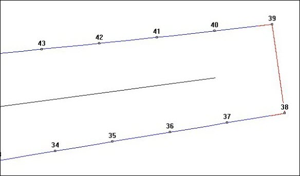
The leading edge, trailing edge, or both ends of some blades can be square shaped.
The PC-DMIS Blade software needs to ensure that the splines do not fit on discontinuities due to the square shape of the blade's trailing or leading edges. If the blade has a square end, you must specify this in the Nominal file.
Example of a Square-End Blade

Example of a square-end blade
The Blade Nominal Editor in PC-DMIS has an option to define blades with square ends. For a detailed procedure, see the documentation in PC-DMIS.
PC-DMIS Blade also offers possibility to define square end of blade.
To define a blade end as square, follow these steps:
Edit the Nominal file. For help, see "Editing a Nominal File".
Choose two points that define corner of the square end (Point number 38 and 39) and specify the end type as square.
In the case where there are sharp corners, you should choose the two corner points to define the square. If the corners are rounded, the blade is NOT a square blade. You can use the "NORMAL" definition.
Example of Blade Nominal File with Square end
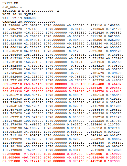
Square corner Nominal file example
Problems with Definition of Square ended Blade
If you define the nose and tail points in the editor and generate a MTH file, you see that the spline of the points do not yield the desired shape. This is because splines by definition try to find a smooth curve that contains all the points defined. At this point, our nominal section curve looks like the following which is not desired.
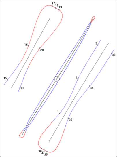
Initial square blade nominal section curve
Make Square Function
The Make Square Function in the PC-DMIS Blade Nominal Editor allows you to define a square end. To do this, follow these steps:
Select Edit | Nominal File to open the Open dialog box. Select the Nominal file to open.
In the Nominal File Editor dialog box, zoom to the nose point area as shown below.

Nominal File Editor dialog box for square-end blades
Identify the three nominal points that define the square end of the blade.
The first point defines the corner point on the CC side of the blade.
The second point defines the corner point on the CV side of the blade.
The third point defines the midpoint between these two points.
The normal vectors of the corner points on the CC side should match the normal vectors of the neighboring points on the CC curve.
Similarly, the normal vector of the corner points on the CV side should match the normal vectors of the neighboring points on the CV curve.
The vector of the middle point should be the end normal vector.
Double-click one of the corner points to highlight it (17 in the above example), and then click Select to define it as one of the corner points.
Although there is no indication that this point is selected, PC-DMIS Blade uses it as if it is selected when you execute the measurement routine.
Double-click the second corner point to highlight it (19 in the above example).
Again, this point may not change color if it was used to define the nose. Also, a single point must separate two numbers. In the above example, the single point 18 separates points 17 and 19.
After you select both corner points, click Make Square. If you did not select the corner points correctly, this error message appears: “Must select two points for corners that are separated by exactly one point”. Otherwise, a prompt displays and asks if it is okay to square off the points. The prompt shows the point numbers that you selected.
Click Yes. PC-DMIS Blade adds 16 points to help better define the corner, four on each side of each corner. The placement of the points is on the line that joins the corner point to its neighbor in each direction. The spacing is a function of the distance to that neighbor.
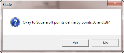
Square corner prompt
The new points insert into the Section Points Text box and add to the graphical display. Repeat this process to square the other end to square off (if both ends are square).
Redefining the Corners
After squaring the end(s), you need to redefine the corner(s) because the point indices have changed. Use the normal PC-DMIS Blade Nominal Editor methods for this process. The procedure for each square end is below.
Double-click the first point in the Section Points Graphical Display window of the Nominal Field Editor screen for the first end of the blade (nose or tail).
Press Ctrl and double-click the second point in the Section Points Graphical Display window of the Nominal Field Editor screen for the same end of the blade (nose or tail).
If the end is the nose of the blade, click Nose and review the settings in the dialog box.
Ensure that the Force as Nose/Tail Point check box is checked.
If the blade is straight, you need to use the force -X option to indicate the convex side.
Ensure that Type of End is set to Square End.
Click OK.
If required, repeat steps 1 through 6 to define the tail end of the blade as square.
Once you have redefined both corners, click OK in the Nominal File Editor dialog box and generate the Math file. The results should define better square ends as shown below:
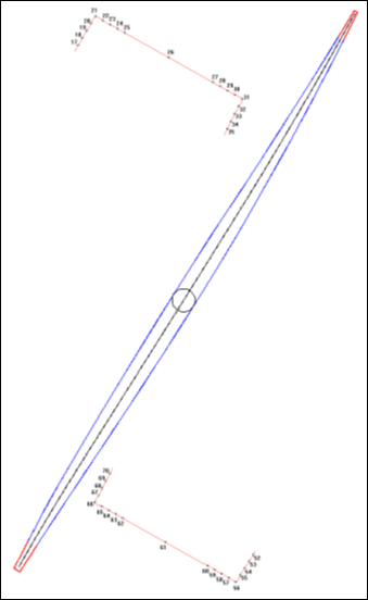
Results of square corner blade
More: