The Variable Tolerancing provides you ability to specify different tolerance for different zone or nominal points of airfoil section and evaluate it accordingly.
PC-DMIS Blade offers variable tolerancing for these calculations:
MAXFORM
MINFORM
LEMAX
LEMIN
TEMAX
TEMIN
How to apply Variable Tolerancing
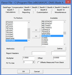
To apply variable tolerancing, select one of the above calculations in creation of the Flavor file.

Flavor File dialog box
To define the method, click Define.
Select the method to define variable tolerance:
NOMFILE - Nominal file
VARIABLE - Variable tolerance file (.VTL)
VARIABLE - Variable in tolerance file
NOMFILE – Nominal File
The Nominal file needs to be modified to add the plus tolerance or minus tolerance for each point. The form of each point in the Nominal file will be X, Y, Z, I, J, K, Minus Tol, Plus Tol. PC-DMIS Blade provides nominal editor to define tolerances for each point in nominal file.
VARFILE - Variable Tolerance File (.VTL)
You need to define two curves for this method. The first curve defines the upper limit of tolerance and second curve defines the lower limit of tolerance. The upper limit and lower limit tolerances curves are defined as sets of 2D points (X,Y). PC-DMIS Blade evaluates if measured curve is within the boundary of upper limit and lower limit curves.
The definition of tolerance curve for each section are stored in Variable tolerance file – VARFILE. The name of the Variable Tolerance file should be the same as the Nominal file but .VTL as the extension. For example, if the name of the Nominal file is MyBlade.NOM, then the name of the Variable Tolerance file should be MyBlade.VTL. Both files should be in the same folder. The order of upper tolerance curve and lower tolerance curve in variable tolerance file is not important.
You can use any text editor to create such a curve.
File Format
The format of each section in the file looks similar to this:
SECTION SECTNAME N1 N2 (N1 and N2 are the number of points that define the two tolerance curves)
X Y (point 1 of first tolerance curve)
X Y (point 2 of first tolerance curve)
…
X Y (point N1 of first tolerance curve)
X Y (point 1 of second tolerance curve)
X Y (point 2 of second tolerance curve)
…
X Y (point N2 of second tolerance curve)
Example
SECTION A-A 800 800
-3.9853,2.1526
-4.1275,2.0513
-4.2696,1.9497
-4.4115,1.8479
-4.5531,1.7458
-4.6946,1.6435
-4.8359,1.5409
-4.9771,1.4380
…
VARIABLE – Variable in Tolerance file
You can add the keywords to define tolerance zone in the Edit Tolerance (.tol) file. You can use any text editor such as Notepad.
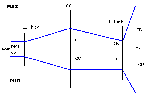
LE_VARTOL (NRT): Followed by the lower and upper tolerances for the entire LE. This is the tolerance in LE area (NRT). It is applied up to LE change points where LE Thick is calculated.
MID_VARTOL (CA&CC): Followed by the lower and upper tolerances. This is the tolerance at the intersection of the Y axis and the CV and CC sides.
TE_VARTOL (CB&CC): Followed by the lower and upper tolerances. This is tolerance at the TE change points where TE Thick is calculated.
CHORD_VARTOL (CD): Followed by the lower and upper tolerances. This is the tolerance applied at the TE area.
Example
LE_VARTOL -0.008 0.008
MID_VARTOL -0.010 0.010
TE_VARTOL -0.012 0.012
CHORD_VARTOL -0.060 0.060
Diagram of Variable Tolerancing Scheme

Variable tolerancing scheme
More: