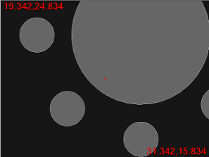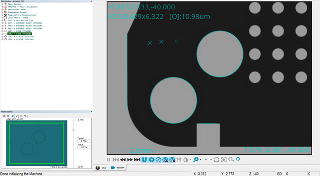

Sample Live View of the Graphic Display window
If the software is in Online mode, the Vision tab shows the actual "real time" view from the video camera.
If the software is in Offline mode, the Vision tab displays a "simulated" view of what a video camera would see, based on the imported CAD drawing. It simulates the geometry and also the illumination. This process is called CAD Camera.

Simulated Live View (CAD Camera)
You can right-click on the image and drag your pointer. This essentially drags the image underneath the camera so that you can position the FOV to a new location on the part. This functionality only works on a DCC machine or when offline.
Display Features in Live View
Features in measurement routines can be displayed in Live View.

Example of features displayed in Live View
All features must have the same camera vector and should be approximately in the same Z height.
To display features in Live View, enable the FindFeaturesInFOVEnable registry entry in the Settings Editor application. For details, see the topic "FindFeaturesInFOVEnable" in the Settings Editor documentation.
Under certain conditions, features in the measurement routine are not drawn in the Live View. This is done to prevent the drawing of out-of-context information or from cluttering the Live View with too much information.
These conditions are:
During the execution of the measurement routine.
When a gage is active on the Live View. You can then move the gage to a feature and use it without the overlay getting in the way.
During the focusing process.
When the Illumination Overlay is active.
When measured or filtered points are shown when editing a feature. This gives you the possibility of looking at the measured point without the overlay getting in the way.
During 2D Profile tracing.
More:
Using the Live View Illumination Overlay