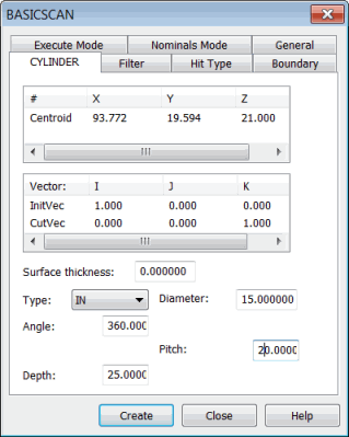
To scan a cylinder feature, select Insert | Scan | Cylinder to open the CYLINDER tab in the BASICSCAN dialog box:
BASICSCAN dialog box - CYLINDER tab
This tab takes parameters such as the cylinder's diameter and pitch and enables the controller to execute the scan.
The cylinder method:
Enables the DISTANCE on the Filter tab.
Enables the VECTOR type on the Hit Type tab.
Does not need a boundary condition set on the Boundary tab.
The Centroid parameter in the # column controls the scan execution. This point is the cylinder center from which the execution starts. You can directly type the center of the cylinder, or you can get it from the machine or CAD.
Defining a Cylinder Basic Scan
You can define a cylinder basic scan in one of these ways:
Directly type the values. See "Cylinder Basic Scan - Type Values Method".
Physically measure the points on the cylinder. See "Cylinder Basic Scan - Measured Point Method".
Click on the cylinder in the CAD model in the Graphic Display window. See "Cylinder Basic Scan - Surface Data Method" or "Cylinder Basic Scan - Wireframe Data Method".
Once you create the scan, PC-DMIS inserts it into the Edit window. Following is an example of a command line for a cylinder basic scan in the Edit window:
SCN1 =BASICSCAN/CYLINDER,NUMBER OF HITS=80,SHOW HITS=NO,SHOWALLPARAMS=YES
<25.399,25.4,0>,CutVec=0,0,1,IN
InitVec=-1,0,0,DIAM=25.4,ANG=360,PITCH=5,DEPTH=0,THICKNESS=0,
PROBECOMP=YES,AVOIDANCE MOVE=NO,DISTANCE=0
FILTER/DISTANCE,1
EXEC MODE=FEATURE,USEHSSDAT=YES,USEDELAYPNTS=NO
BOUNDARY/
HITTYPE/VECTOR
NOMS MODE=MASTER
ENDSCAN
More:
Cylinder Basic Scan - Type Values Method
Cylinder Basic Scan - Measured Point Method
Cylinder Basic Scan - Surface Data Method