 and Surface mode
  icons with the
Program mode
icons with the
Program mode  icon
to take offline hits on your CAD model's wireframe or surface entities.
icon
to take offline hits on your CAD model's wireframe or surface entities.From the Operation | Graphic Display Window | Change Curve/Surface Mode menu, you can choose between Curve mode or Surface mode. These make a models curves (the wireframe model) or its surfaces visible and available for selection.
From the Graphic Modes toolbar, you can also use the Curve mode and Surface mode icons with the
Program mode icon
to take offline hits on your CAD model's wireframe or surface entities.
You must have the optional package called "Curves and Surfaces" purchased for your system in order to access these modes.
Curve Mode
The
Curve mode option makes a wireframe's model
of curves and lines selectable when you click on the CAD data in the Graphic
Display window. You must import a wireframe model for this option to become
available. This mode works well for all measured
features.
You need two graphic views to take hits in Curve mode. You can set up multiple graphic views from the View Setup dialog box. For information on how to do this, see "Setting Up the Screen View".
The picture below illustrates this feature. The top half of the screen (A) shows the model in the Z+ view. The bottom half of the screen (B) shows the model in the Y- view. If your workplane is the Z+ plane, you can then use top half of the screen (A) to take hits, and use the bottom half of the screen (B) to set the probe's depth.
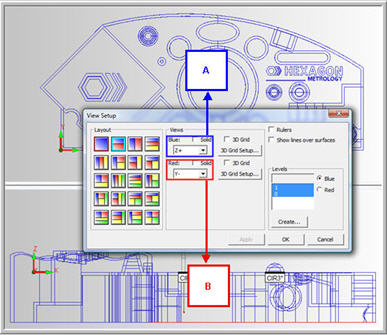
Sample Graphic Display window split to show two different wireframe views of the part
The following list references the above screen as it discusses the Curve mode mouse operations you can use to set your probe's depth and take hits to insert measured features into your measurement routine. The information below assumes that Z+ is your workplane. You must also set PC-DMIS in Program mode for these to work:
Operation: Right-click
Screen to Use: B
Description: This sets the approximate animated probe depth at the current mouse pointer position. Use this to create Move Points when you create measurement routines in Offline mode. See "Inserting a Move Point Command" in "Inserting Move Commands".
Operation: Right-click + drag
Screen to Use: B
Description: This sets the depth for your next inserted hits on the nearest wireframe entity when you release the mouse button. Use this to set the depth for measured lines, circles, and cylinders.
Operation: Left-click
Screen to Use: A
Description: This selects the nearest line or circle and takes equally-spaced hits at the current depth setting based on the settings in the General tab of the Setup Options dialog box. See "Other Edit Boxes for the General tab" in "Setting Your Preferences".
Operation: Left-click + drag
Screen to Use: A
Description: This takes a single hit at the current depth setting on a line, arc, or circle. The hit direction depends on which side of the wire you release your mouse. Always approach from the side of the wire the machine would approach from.
Operation: Left-click + hold and release
Screen to Use: A
Description: This delayed click takes a hit at the pointer's position at the current depth setting. Use this method to take hits on a plane. Be sure to hold the mouse steady when you hold down the button so that when you release it, a valid hit is taken normal to the surface at the pointer's position.
For example, to define a Measured Cone feature in the Z+ view in Curve mode, perform a right-click + drag operation in screen A on the cone's top circle and then left-click on the circle to insert four hits. Right-click + drag again on the bottom circle again in screen A and then left-click again on the circle to insert four more hits. You should have eight hits each at different depths. Press END to create the Measured Cone feature.
You must have an active Internet connection to see this video.

Surface Mode
The
Surface mode option makes a solid model's surfaces
selectable when you click on the CAD data in the Graphic Display window.
You must import a solid model for this option to become available.
To take a hit, click on any surface. PC-DMIS pierces the surface and captures
the X,Y,Z,I,J,K information; the hit is recorded at the pointer's position.
Select the correct number of hits to define the feature and then press
the END key. PC-DMIS will guess the feature type. This mode works best
for creating point, line, and plane features. While you can also use this
mode with circular features (circles, cylinders, cones, and spheres),
you will find that it is often difficult to select hits at a constant
cross section or depth, especially for inside features. In these cases,
you may want to use Curve mode.
For information on using these modes with scans, see the "Scanning Your Part" chapter.