To create a Roughness scan command (RGHSCN), do the following:
Select Insert | Scan | Roughness to open the Roughness Scan dialog box:
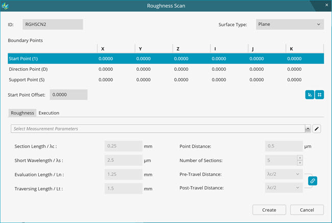
Roughness Scan dialog box
Complete the options:
ID box - Use this box to enter the name of the Roughness scan command.
Surface Type box - This option provides the ability to measure on different types of surfaces. Currently, Plane is the only available surface type. With this Plane surface type, you can measure the roughness of planer surfaces and cylindrical surfaces along the axis of the cylinder where the sensor can physically fit.
Boundary Points area - The options in this area define the start and direction of the roughness scan line:
Start Point (1) - Type the X, Y, Z, I, J, and K values for the start point. The roughness needle starts the scan from this point. The start point is at a pin-to-needle distance from support point. PC-DMIS records scan points from this point. The roughness probe file contains the definition of the pin-to-needle distance. For more information about this file, refer to the "Creating a Roughness Probe File" topic.
Direction Point (D) - Type the X, Y, Z, I, J, and K values for the direction point. This point indicates the direction of the roughness scan line. The roughness scan must be performed across the face of the machined surface.
Support point (S) boxes - Type the X, Y, Z, I, J, and K values for the support point. The roughness sensor support pin probes this point.
Start Point Offset box - Type the value for the Start Point Offset. The start point offset may be required if there is a gap between the support point and the start point as shown in the image below. Note that the traverse length is inclusive of the start point offset.
To get the support point at the desired position, select Support Point from the menu and then click on the CAD at the desired location. This is point S.
Next, click on the CAD again to define the direction. This is point D.
Finally, type the value in the Start Point Offset box to move the start point to the desired location. This is point 1. It is the start of the roughness scan.

Example Support Point (S), Start Point Offset (1), and Direction (D)
 Snap
On button - Many users prefer to create scan lines that
are parallel to the coordinate axis. To help align a D point in
line with an S point along the nearest coordinate axis, click
this button.
Snap
On button - Many users prefer to create scan lines that
are parallel to the coordinate axis. To help align a D point in
line with an S point along the nearest coordinate axis, click
this button.
 Snap
Off button - If you do not want to create scan lines that
are parallel to the coordinate axis, click this button.
Snap
Off button - If you do not want to create scan lines that
are parallel to the coordinate axis, click this button.
 Show
Cartesian button - To display the coordinates of the boundary
points in the Cartesian coordinate system, click this button.
By default, boundary points appear in the Cartesian coordinate
system.
Show
Cartesian button - To display the coordinates of the boundary
points in the Cartesian coordinate system, click this button.
By default, boundary points appear in the Cartesian coordinate
system.
 Show
Polar button - To display the coordinates of the boundary
points in the Polar coordinate system, click this button.
Show
Polar button - To display the coordinates of the boundary
points in the Polar coordinate system, click this button.
Complete the scanning parameters on the Roughness tab.
Complete the scanning parameters on the Execution tab.
Do one of the following:
To add the Roughness scan command to the Edit window, click Create.
If the current tip angle of the roughness probe does not match the scan line direction that you selected, PC-DMIS adds a Tip command (TIP) to the Edit window. Ensure that the move points around the Tip command are set as required to avoid any collision.
To cancel your changes and the creation of the Roughness scan command, click Cancel.
More: