In this Topic Hide
A position specification controls how much the considered feature or features can deviate from a specified position relative to zero or more datums.
For this geometric tolerance, these three aspects work together:
Each considered feature and each resulting toleranced feature
Each tolerance zone
The datum features (if any are referenced)
To evaluate this tolerance, PC-DMIS converts each considered feature to a toleranced feature. You can find this described in "Deriving the Toleranced Feature”.
PC-DMIS then optimizes each toleranced feature into its respective tolerance zone. The optimization process respects whatever constraints each datum imposes. When there are multiple considered features, the optimization process simultaneously considers all features, so that all toleranced features are fitted into their tolerance zones at once. This process is similar to a physical gage, where all of the gage pins must fit into the workpiece's holes at the same time.
You can use these feature types:
spheres, 3D surfaceless points, cylinders, circles, cones, widths, slots, notches, constructed mid planes, constructed mid lines, and constructed mid points.
ASME position tolerances also allow 3D constructed BF lines. ISO position tolerances also allow planes, lines, and surface points.
3D constructed BF lines, spheres, cylinders, circles, cones, widths, slots, and notches have a toleranced feature that is different than the considered feature’s surface data. For information, see "Deriving the Toleranced Feature".
Different tolerance zone shapes are allowed for different types of features. For information about the feature command types that refer to different feature types, see "Feature Types With and Without Surface Data".
Point-like
considered features
When the considered feature is point-like, the tolerance zone shape may
be planar, diametrical, or spherical. These are point-like considered
features:
sphere or 3D surfaceless point
From left to right, the pictures below show FCFs with a planar, diametric, and spherical tolerance zone when the considered feature is a sphere:


Planar and diametric tolerance zones on point-like considered features need a specified tolerance zone orientation, because the feature does not have enough information to orient the zone correctly. In these cases, the Zone Orientation button in the Geometric Tolerance dialog box becomes visible. For information on how to use this button to change the zone orientation, see "Zone Orientation" in the "Feature Control Frame Tab" topic.
Examples
If a position tolerance controls the X component of the position (planar
tolerance zone), the tolerance zone surface normal vector should be
X.
If a position tolerance controls the X and Y components of the position (diametric tolerance zone), the tolerance zone axis vector should be Z.
Axial
Considered Features
When the considered feature is axial, the tolerance zone may be planar,
diametrical, radial arc, or perpendicular to radial. These are axial considered
features:
cylinder, circular cross section of a cylinder, cone, or surfaceless axis
A diametric tolerance zone is shown below, using the diametric zone symbol.

Planar zones, radial arc zones, and perpendicular to radial zones do not use any tolerance zone shape symbol, and are shown below.
Planar tolerance zones on axial considered features need a specified tolerance zone orientation, because the feature does not have enough information to orient the zone correctly. In these cases, the Zone Orientation button in the Geometric Tolerance dialog box becomes visible. For information on how to use this button to change the zone orientation, see "Zone Orientation" in the "Feature Control Frame Tab" topic. This button also allows users to specify a radial arc or perpendicular to radial zone.
If a position tolerance controls the X component of the position, the tolerance zone surface normal vector should be X.
Plane-Like
Considered Features
When the considered feature is plane-like, the tolerance zone is always
planar and oriented parallel to the nominal surfaces. These are plane-like
considered features:
plane, surface line, width, slot, notch, surface point, or mid-point
You can have more than one considered feature, but those features must all be the same type.
Be careful with slots and notches.
You should only use them if you already know that the form of the features is very good. If you suspect that the manufactured form error might be significant, do not use a slot or notch command. Instead, measure a scan around the perimeter of the feature and then tolerance the form, orientation, and location of the feature with a profile of a line tolerance.
Actual Value:
Each considered feature has its own actual value. This is the size of the
smallest tolerance zone that contains the actual toleranced feature. The
zone is nominally oriented and located to each actual datum, with some
exceptions detailed in "How
PC-DMIS Solves Datums". When the position tolerance contains
more than one considered feature, and the datum reference frame is not
fully constrained, an optimization procedure must simultaneously fit all
toleranced features in their respective tolerance zones if possible.
Measured Value:
Each considered feature has its own measured value. This is the size
of the smallest tolerance zone that contains the measured toleranced feature.
The zone is nominally oriented and located to each measured datum, with
some exceptions detailed in "How
PC-DMIS Solves Datums". When the position tolerance contains
more than one considered feature, and the datum reference frame is not
fully constrained, the PC-DMIS optimization procedure simultaneously fits
all toleranced features into their respective tolerance zones in a proportional
way, which guarantees all toleranced features will fit in their respective
tolerance zones if at all possible.
Suppose you have this position specification:

With the above specification, the actual value looks like this:

The actual part surface uses the solid line, the actual toleranced features are the small crosses, and the smallest tolerance zones containing the actual toleranced features are shown in the shaded areas. The tolerance zones are nominally located and oriented with respect to each other and with respect to the datum.
Considered features must have some nominal location and orientation to each datum feature.
All input features (considered and datum) must have the correct specified nominal values. This ensures that the measured values are calculated correctly, and that the tolerance command correctly identifies the optimizable degrees of freedom.
For a planar zone on axial features, the datum reference frame must fully constrain the tolerance zone orientation. The planar tolerance zone’s surface normal must be perpendicular to each considered feature's axis vector.
For radial arc and perpendicular to radial tolerance zones on axial features, follow these requirements:
The datum reference frame must establish a clear polar origin and polar axis.
The axial features must be nominally parallel to the polar axis.
When the considered feature
is a cylinder, sphere, or width, position tolerances allow a maximum material
modifier  to indicate the specification is at the maximum material condition (MMC).
Alternatively, they allow a least material modifier
to indicate the specification is at the maximum material condition (MMC).
Alternatively, they allow a least material modifier  to indicate the specification is at the least material condition (LMC).
This means that as the unrelated mating envelope size (or unrelated minimum
material envelope size for LMC) deviates from the MMC (or LMC), additional
tolerance or "bonus" tolerance is added to the tolerance in
the feature control frame, yielding a total tolerance. For more information
on this bonus tolerance, see "Evaluating
Size with the Geometric Tolerance Command".
to indicate the specification is at the least material condition (LMC).
This means that as the unrelated mating envelope size (or unrelated minimum
material envelope size for LMC) deviates from the MMC (or LMC), additional
tolerance or "bonus" tolerance is added to the tolerance in
the feature control frame, yielding a total tolerance. For more information
on this bonus tolerance, see "Evaluating
Size with the Geometric Tolerance Command".
This example is in inches. Suppose a cylindrical hole has a position tolerance 0.08 at MMC, as shown here:
The size tolerance is 0.675 plus or minus 0.025, meaning the range of acceptable sizes is 0.650 to 0.700. The maximum material condition is then 0.650. If the unrelated measured mating envelope size is 0.661, then the bonus tolerance is 0.011, and the total tolerance is 0.091.
When the considered feature
is an auto feature cylinder, you can use a projected-zone modifier  .
This projects (extrapolates) the measured feature axis as described in
"Deriving the Toleranced
Feature".
.
This projects (extrapolates) the measured feature axis as described in
"Deriving the Toleranced
Feature".

When the considered feature has surface data and the toleranced feature differs from the considered feature's surface data (spheres, cones, cylinders, circles, widths), the feature math type controls how to compute the tolerance feature from the considered feature's surface data. For information, see "Deriving the Toleranced Feature”.
When at least one datum feature has surface data, the datum math type controls how to compute the measured datums from the datum features' surface data. For more information, see "How PC-DMIS Solves and Uses Datums".
Slots can be considered in either a lengthwise or a widthwise fashion, as described in "Lengthwise_versus_Widthwise_Slots".
A position tolerance with multiple segments is called a “composite position”. Composite position tolerances are typically specified on a pattern of features. The first (or upper) segment of a composite position is the same as a single segment position as described in the preceding sections of this page. All lower segments of a composite position are subtly different. This is because the tolerance zones of the pattern have unlocked translation compared to the datum reference frame. However, the tolerance zones remain nominally located and oriented to each other.

The datum reference frames for the lower segments of a composite position follow these rules:
Each datum reference frame must only use the same datums as the reference frame above it.
The datums must be in the same order.
The datums must have the same modifiers.
A lower segment can have fewer datums than the segment above.
Suppose the upper segment has datums ABC. The lower segment then could reference no datums, datum A, datums AB, or datums ABC. But it could not reference datums BA nor AC nor ABD.
Here are some examples of allowed composite position tolerances:


Here are some examples of not-allowed composite position tolerances:


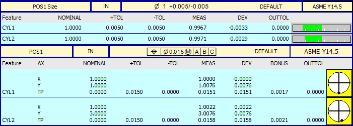
Here is an example report for a position tolerance of two cylinders. The cylinders' size tolerance is in the upper label, and the diametric-zone position is in the lower label. The lower label includes information for the XY positions of the cylinders, in the optimized frame (not in the current alignment).