
In this Topic Hide
A symmetry specification controls how much the feature can deviate from being symmetric about one or more datums.
For this geometric tolerance, these three aspects work together:
Each considered feature and each resulting toleranced feature
Each tolerance zone
The datum features
To evaluate this tolerance, PC-DMIS converts each considered feature to a toleranced feature. You can find this described in "Deriving the Toleranced Feature”.
PC-DMIS then optimizes each toleranced feature into its respective tolerance zone. The optimization process respects whatever constraints each datum imposes.
You can use these feature
types:
widths, constructed mid planes, constructed mid lines, and constructed
mid points
PC-DMIS constructs the toleranced feature differently based on the standard you use (ASME Y14.5 or ISO 1101).
ISO 1101 (or with a constructed mid feature or a 1D width):
PC-DMIS constructs the toleranced feature in the same ways as position toleranced features do.
ASME Y14.5 with a 2D or 3D width:
PC-DMIS provides an option to switch between MEDIAN_POINTS or AXIS:
AXIS - The software constructs the toleranced feature as the axis (center-plane) of the unrelated mating envelope (this is the same as position tolerances).
MEDIAN_POINTS - The software constructs the toleranced feature from all median points of the width. It does this according to paragraph 7.7.2 of ASME Y14.5 2009.
The tolerance zone shape is always planar. It is oriented parallel to the nominal surface or surfaces.
Actual Value:
This is the size of the smallest tolerance zone that contains the actual
toleranced feature. The zone is nominally oriented and located to each
actual datum.
Measured Value:
This is the size of the smallest tolerance zone that contains the measured
toleranced feature. The zone is nominally oriented and located to each
measured datum.
Suppose you have this symmetry specification:

With the above specification, the actual value looks like this:
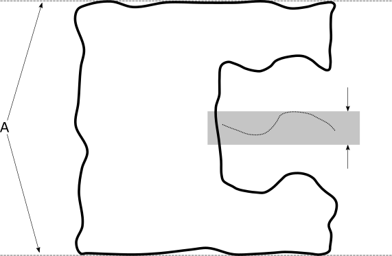
The actual part surface uses the solid line, the actual datum uses the dashed line, the toleranced feature uses the dotted line, and the smallest tolerance zone containing the actual toleranced feature is shown in the shaded area. The tolerance zone is exactly symmetric to the center-plane of the actual datum.
Finally, the measured value (with DEFAULT datum math) looks like this:
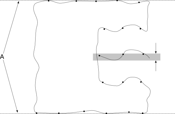
The measured tolerance zone is exactly symmetric to the center-plane of the measured datum. In this case, the measured points were not measured densely enough, and so the measured value is smaller than the actual value.
All input features (considered and datum) must have the correct specified nominal values. This ensures that the measured values are calculated correctly, and that the tolerance command correctly identifies the optimizable degrees of freedom.
The considered feature surface or surfaces must be nominally symmetric with the datum reference frame.
When the considered feature
is a width, symmetry tolerances referencing ISO 1101 allow a maximum material
modifier  to indicate the specification is at the maximum material condition (MMC).
Alternatively, they allow a least material modifier
to indicate the specification is at the maximum material condition (MMC).
Alternatively, they allow a least material modifier  to indicate the specification is at the least material condition (LMC).
This means that as the unrelated mating envelope size (or unrelated minimum
material envelope size for LMC) deviates from the MMC (or LMC), additional
tolerance or "bonus" tolerance is added to the tolerance in
the feature control frame, yielding a total tolerance. For more information
on this bonus tolerance, see "Evaluating
Size with the Geometric Tolerance Command".
to indicate the specification is at the least material condition (LMC).
This means that as the unrelated mating envelope size (or unrelated minimum
material envelope size for LMC) deviates from the MMC (or LMC), additional
tolerance or "bonus" tolerance is added to the tolerance in
the feature control frame, yielding a total tolerance. For more information
on this bonus tolerance, see "Evaluating
Size with the Geometric Tolerance Command".
Symmetry tolerances have a feature math type when the considered feature is a width.
This math type controls how to compute the toleranced feature from the considered feature's surface data. For more information, see "Deriving the Toleranced Feature".
When at least one datum feature has surface data, the datum math type controls how to compute the measured datums from the datum features' surface data. For more information, see "How PC-DMIS Solves and Uses Datums".
For many years, with PC-DMIS symmetry tolerances, you could input pairs of planes, pairs of lines, pairs of points, or pairs of sets. Originally, this was because PC-DMIS did not have a width command. Starting in PC-DMIS 2020.2, these kinds of considered feature pairs are no longer allowed. Each considered feature has its own measured value, and that means the best way to use a symmetry command is with a width feature. PC-DMIS has special handling for migrating XactMeasure symmetry tolerances to the new geometric tolerance command as seen in "Symmetry" in "Migration to Constructed Input Features".
Here is an example report for a symmetry tolerance of a mid-line.
