
The CadReportObject (CRO) lets you view your CAD drawing inside a finished report. When you initially drop the CRO into a report template, PC-DMIS automatically launches the Label Layout Wizard. After using this wizard to position the labels you want PC-DMIS to use, you will see a dummy graphic of the Hexagon test block, and if no rules are defined, dummy labels as well. It will look something like this:
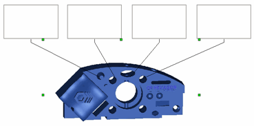
A sample CRO inserted into a report template
Remember, these dummy items are simply representations of what you want on your report. In the actual Report window, it shows the actual CAD model. The labels display a picture of the label template defined by the first rule in the rule tree of the CRO. If the label is not associated, and no rules apply, it draws the dummy label image.
How it Works in the Report Window:
In the Report window, your CAD display initially appears exactly as shown in your Graphic Display window when it finishes executing your measurement routine or at the time you redraw your report, except that it does not zoom in any closer. If you make modifications to a CRO in the Report window, PC-DMIS retains those changes to the CAD image on the report—even after subsequent measurement routine executions—until you right-click on the CAD view(s) inserted into your report and select Remove Object Modifications or until you select File | Reporting | Clear Template Associated Data.
While your Report window often shows your entire CAD drawing, it only shows labels and leader lines for those features you have specified in the Rule Tree Editor. For example, if your measurement routine has four measured circles and two measured lines, yet in the Rule Tree Editor your CRO displays labels only for the measured circles, then the report only shows label information for those circles, even though you may have measured the lines as well in your last execution.
Also, if a CRO is configured to display—using the Label Count list on the Label Layout Wizard—a fewer number of labels than the number of features it is specified to report on in the Rule Tree Editor, then the Report window displays additional instances of your CAD drawing on additional pages in the Report window. These additional images show leader lines and labels to any remaining features. This is especially helpful if your labels have a lot of information that may make your report look cluttered if you have more than one or two labels around a part drawing.
If you're using viewsets, your CAD display appears exactly as shown in your viewsets. PC-DMIS inserts a new CAD display on a new page of the report for each viewset encountered during execution. For information on viewsets, see "Working with Viewsets".
Rotating, Moving, and Zooming the CRO CAD Image
You can change the CRO CAD image orientation and zoom level in the Report window, or move it to a new location.
To rotate the image, double-click on the object to "activate" it. Once activated, click and hold the wheel button. As you do this, drag the mouse. You can also press Ctrl and right-click while dragging the mouse.
To zoom in or out of the image, double-click the object to "active" it. Once activated, rotate your mouse's wheel button to zoom in and out.
To move the CRO, right-click the object to select it. Once selected, click the object and drag the mouse.
To cancel zoom or rotation changes, press the Esc key. The CRO is "deactivated" without applying your changes.
To save zoom or rotation changes, double-click outside of the CRO. The CRO is "deactivated", and the CAD image uses the new orientation and zoom level. If you are using the Feature-based label layout on the CRO, the entire report is reloaded with the new orientation and zoom level applied to the CAD image. If the CRO is from a SNAPSHOT command, PC-DMIS applies these same changes to your SNAPSHOT command in the Edit window.
To save movement changes, click outside of the selected object.
To remove pan, zoom, and rotate modifications for the CRO, right-click on the object in the Report window, and choose Remove CAD Report Object Pan/Zoom/Rotate MOD. Other mods (such as section cuts, various label definitions, solid or wire displays, and so forth) are not affected.
Switching Between Solid and Wireframe Modes
In the Report window, you can do this by right-clicking the CRO and selecting the Wireframe menu item from the shortcut menu.
In the Report Template Editor, you can do this by right-clicking the CRO, accessing the Properties dialog box and setting the Wireframe property to either YES or NO.
Additional Functionality in the Custom Report Editor
In the Custom Report Editor,
if you activate a CRO,
the View Setup icon  on the
Graphic Modes toolbar becomes available for
selection. The Edit | CAD Operation | View Setup
menu item also becomes available. Clicking this icon or selecting the
menu item displays the View Setup dialog box.
In this context, you can use this dialog box to only modify the display
of the CRO
just as you would manipulate the view of the Graphic Display window normally.
See "Setting
Up the Screen View" for information on using the View
Setup dialog box to define views.
on the
Graphic Modes toolbar becomes available for
selection. The Edit | CAD Operation | View Setup
menu item also becomes available. Clicking this icon or selecting the
menu item displays the View Setup dialog box.
In this context, you can use this dialog box to only modify the display
of the CRO
just as you would manipulate the view of the Graphic Display window normally.
See "Setting
Up the Screen View" for information on using the View
Setup dialog box to define views.
Choosing Wireframe or Solid:
You can display your CRO
in Custom Report Editor as either a solid or wireframe by using the
View Setup dialog box and marking or clearing
the Solid check box. Alternately, with the
object only selected but not activated, you can right-click on the
CRO, select
Properties from the shortcut menu and then
set the Wireframe property to either YES
or NO. PC-DMIS toggles between a solid or wireframe in your custom
report.
Viewing Levels:
You can use the View Setup dialog box to
select specific levels of CAD elements to be applied to the object
in the Custom Report Editor. The Levels
area lists any predefined CAD levels.
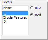
Levels area showing three levels
Select one or more levels and click OK, PC-DMIS displays the selected levels on the selected CRO in your custom report. For information on creating your own levels, see "Working with CAD Levels" in the "Editing the CAD Display" chapter.
Mirroring
the CAD:
PC-DMIS lets you mirror the CAD image contained in that object in the
Custom Report Editor. To do this, select the CRO,
select Edit | CAD Operation | Mirror. The
Mirror CAD dialog box appears:
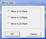
Mirror CAD dialog box
This dialog box lets you create a mirror image of the part. Select the plane (axis) in which you want to mirror the part, and click OK. PC-DMIS displays the mirrored CAD model on the selected CRO. See "Transforming a CAD Model" for additional information on Mirroring CAD in the Graphic Display window.
See "Creating Custom Reports" for information on custom reports.
Using Image Caching
PC-DMIS lets you cache your part's image once and use the image cache later in reporting contexts instead of always using your measurement routine's associated .cad file. You may find this useful in situations where you have a very large .cad file that takes a long time to load into the Graphic Display window. Once you cache your images for a particular report you won't need your .cad file to view that report.
To cache your image:
Close PC-DMIS and open the PC-DMIS Settings Editor.
Under the Reporting section, set the UseImageCachingScheme registry entry to 1.
Close the PC-DMIS Settings Editor and restart PC-DMIS.
Load the measurement routine and the .cad file as usual.
Open the Report window and select a report template that uses the CRO.
Generate the report.
Make any desired modifications to the CRO items used in the report.
Print your report.
This process caches the images used in this particular report. Now if you delete (or rename) your .cad file to speed up the measurement routine opening process, this same report uses your cached images. Note that other reports that use the CRO are not cached however, and you need to load the .cad file as usual.
Properties:
Many of the properties in this table are covered in more detail in the "Label Layout Wizard" topic.
AutoZoom
Determines if the object automatically zooms and focuses attention on only
that portion of the CAD model where label objects are currently displayed.
Draw wires in shaded mode
This determines whether or not PC-DMIS displays a wireframe of the CAD
object on top of the shaded image when viewing the CAD model in a solid
surface view.
Label Layout
This opens the Label Layout Wizard. This lets
you quickly layout multiple labels around your CAD drawing. See "The
Label Layout Wizard" for more information.
Leader Line ArrowHeader Height
Defines the height of the arrow on the leader line.
Leader Line ArrowHeader Style
Defines the style of the arrow on the leader line.
Leader Line Color
Defines the color of the leader line.
Leader Line ending at two features for angle
Determines if the leader line splits to point to both features.
Leader Line ending at two features for distance
Determines if the leader line splits to point to both features.
Leader Line Feature Mode
Determines whether the leader line points to the feature's centroid or
to the usual drawn location.
Leader Line Style
Defines the style of the leader line.
Leader Line Termination
This draws the leader line from the label to either the Measured
feature on the CAD or the Nominal feature on
the CAD. See description in the Label
Layout Wizard.
Leader Line Width
This defines the width of the leader line in pixels.
RuleTree
This opens the Rules Tree Editor dialog box.
This dialog box lets you define conditions and actions for this object.
See "About the Rule Tree
Editor" for more information.
ShowBorder
This draws or hides a border around the CRO.
Single Click Rule Tree
This lets you browse and select a label template that PC-DMIS displays
when you click on a label from the Report window.
TrihedronShow
Shows or hides the trihedron on the CAD image.
0 - No - (default) Hides the trihedron.
1 - Yes - Shows the trihedron.
Wireframe
This property lets you show the CRO
in your report in either a wireframe (if set to YES)
or solid surface view (if set to NO).
Hide
all measured features
Shows or hides features on the CAD image.
0 - No - Shows features.
1 - Yes - Hides features.
2 - Use registry setting - (Default) Uses the registry default. This can override the HideAllMeasuredFeaturesOnReport registry entry located in the Reporting section of the PC-DMIS Settings Editor.
Hide
all points
Shows or hides point features on the CAD image.
0 - No - Shows point features.
1 - Yes - (default) Hides point features.
2-Use registry setting - Uses the registry default. This can override the HideAllPointsOnReport registry entry located in the Reporting section of the PC-DMIS Settings Editor.
Colormap is own page
Shows a colormap alone on its own page or with other objects. This property
works with pointclouds (COP) Surface
Colormaps; it does not affect Profile dimensions that have an embedded
colormap.
0 - No - The colormap resides with other objects, and the report does not add a new page with only the colormap.
1 - Yes - (default) The report adds an additional page before the usual colormap page with only the colormap and its color key.
More: