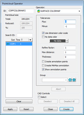
Pointcloud Operator dialog box - SURFACE COLORMAP Operator
The SURFACE COLORMAP operation applies a colored shading to the CAD model. The model is shaded according to the deviations of the pointcloud compared to CAD. The model uses the colors defined in the Edit Dimension Colors dialog box and the tolerance limits specified in the Upper tolerance and Lower tolerance boxes discussed below.
The colors used for the colormap are defined in Edit Dimension Colors dialog box (Edit | Graphic Display Window | Dimension Colors).
Show / Hide Colormaps
You can show or hide colormaps in the Graphic Display window in different ways. When hidden, PC-DMIS does not show the colormaps in the Graphic Display window as you move through the Edit window.
The Activate Colormap button
has two states: Enabled and Disabled. Click the Activate
Colormaps button ( )
from the Graphics Items toolbar or from the
menu (Operation | Graphic Display Window | Graphic
Items | Activate Colormaps) so it's in the enabled state (
)
from the Graphics Items toolbar or from the
menu (Operation | Graphic Display Window | Graphic
Items | Activate Colormaps) so it's in the enabled state ( ). Colormaps are now actively shown in the Graphic Display
window.
). Colormaps are now actively shown in the Graphic Display
window.
To hide the colormaps in the Graphic Display window,
click the Activate Colormaps button again so
it's in the disabled state ().
You can also select None from the Colormaps
list to disable colormaps.
To show the colormaps:
Click the Activate Colormaps button so it's in the enabled state. When you enable this button, PC-DMIS displays the colormaps in the Graphic Display window based on the cursor position in the Edit window.
Select a colormap from the Colormaps list.
When you apply or execute a colormap, PC-DMIS automatically sets the Activate Colormaps button to the enabled state.
When the cursor is on a Mesh, Point, Surface or Thickness colormap in the Edit window, the active colormap appears in the Graphic Display window. PC-DMIS also displays the Colormap ID in the Colormap combo box.
If your cursor is above all the colormaps in the Edit window, PC-DMIS does not show any colormap in the Graphic Display window, and sets the Colormap combo box to None.
Select View | Other Windows | Dimension Colors to view the color scale from the Dimension Colors Bar.
To apply the SURFACE COLORMAP operation to a Pointcloud,
click the Pointcloud Surface Colormap button
( )
on the Pointcloud toolbar (View
| Toolbars | Pointcloud), or select Insert |
Pointcloud | Surface Colormap.
)
on the Pointcloud toolbar (View
| Toolbars | Pointcloud), or select Insert |
Pointcloud | Surface Colormap.
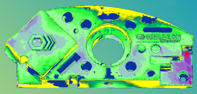
Example of a Surface COLORMAP applied to selected CAD elements
The SURFACE COLORMAP operator has these options:
Tolerances - Use this option to set the upper (Plus) and lower (Minus) tolerance values:
Use dimension color scale check box - When you select this check box, the software defines the color bar used for the Surface Colormap color properties by the Dimension Colors Bar. For details on the Dimension Colors Bar, see "Using the Dimension Colors Window (Dimension Colors Bar)" in the "Using Other Windows, Editors, and Tools" chapter of the PC-DMIS Core documentation.
Edit Color Scale - When you clear the Use dimension
color scale check box, PC-DMIS enables the Edit
Color Scale button. When you click this button, the functionality
to dynamically change the color, scale, and threshold of the surface and
point colormap properties becomes available through the Color
Scale Editor dialog box. For details, see the "Edit
the Color Scale" topic.
No data color check box - When you select this check box, the software maps the selected color to areas on the selected surfaces where no data is found.
Refine Factor - This option adjusts the accuracy of the Surface colormap. If you change this value, PC-DMIS draws a new and changed colormap. The underlying measured data does not change. The colormap tessellates the CAD model with an overlay of colored triangles. The vertices of each triangle are colored with the color that corresponds to its deviation from the pointcloud. The colors are taken from the dimensions color scale discussed above. By using a smaller or larger refine factor value, you can generate a finer or coarser tessellation, respectively. You may want to decrease the refine factor to obtain a smoothly shaded CAD with a more accurate deviation representation. However, setting a smaller refine value results in a larger number of triangles, thereby increasing the computation time and the size of the CAD model. For comparison, note that the number of triangles for a refine factor of 0.5, compared to a refine factor of 1.0, is about 4 times more; whereas a refine factor of 0.1 compared to 1.0, is about 100 times more.
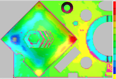
Pointcloud COLORMAP example with a Refine Factor of 1:
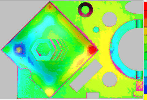
Pointcloud COLORMAP example with a Refine Factor of 0.1:
Max distance - The software only includes points that fall within the Max distance value as part of the colormap. Note that if this value is too small, you may not see all the expected colored deviations. A good rule of thumb is to set this value slightly larger (10%, for example) than the largest deviation.
Thickness - This option adds a thickness value to deviations on the colormap. This is useful if you want to add a material thickness to a CAD surface model.
Create annotation points check box - Annotations are a way to display the deviation for a specific location on a surface colormap with its associated color. To create an annotation:
Select the Create annotation points check box. This clears the Select check box in the CAD Controls area and disables most of the options on the right side of the dialog box.
Select a point on the CAD surface in the Graphic Display window. PC-DMIS evaluates and creates an annotation label in the same background color as the COP deviation point with the deviation value. You can move the label around in the Graphic Display window as any other label.
Once created, the annotation labels remain in the same position and have the same characteristics if you restart the measurement routine, or if you restart PC-DMIS and you reload the same measurement routine.
Create MinMax annotations check box - When you select this check box, the software creates the minimum and maximum values and displays them as annotation labels for the active COP Surface Colormap.
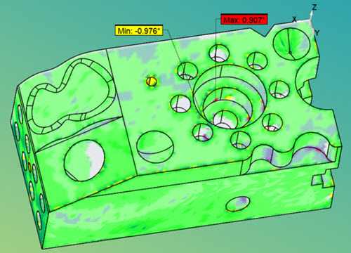
PC-DMIS calculates the minimum and maximum points each time you execute the measurement routine.
Show, Hide, or Delete Annotation Labels
To show, hide, or delete annotation labels, right-click one to display the pop-up menu and then select the appropriate option.
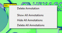
Delete Annotation - The software deletes the selected annotation label.
Show All Annotations - The software displays all annotation labels.
Hide All Annotations - The software hides all annotation labels.
Delete All Annotations - The software deletes all annotation labels.
Show annotation points check box - When you select this check box, the software displays all annotation points.
Group - You can use this option to create, modify, or identify Surface Colormap groups. For details, see "Method 2" in the "Apply COLORMAP to a CAD model with Multiple Surface Profile Tolerances" topic.
Click Abort to undo any calculations that were generated after you click the Apply button.
CAD Controls - This option lets you apply the operation to the CAD elements you select. For details, see the scan area of the "CAD Controls" topic.
Click Create to insert a COP/OPER,SURFACE COLORMAP command into the Edit window.
For example:
COPFCOLMAP2=COP/OPER,SURFACE COLORMAP,PLUS TOLERANCE=0.25,MINUS TOLERANCE=-0.25,THICKNESS=0
REF,COP1,,
Colormaps in the Report
For information on how the software shows colormaps in the report, see "Colormaps and the CadReportObject" in the "Reporting Measurement Results" chapter of the PC-DMIS Core documentation.
More:
Apply COLORMAP to a CAD model with Multiple Surface Profile Tolerances
Dimensioning Surface Profile Using the Pointcloud Surface COLORMAP