
Pointcloud Operator dialog box - POINT COLORMAP Operator
The Point Colormap operation evaluates the deviations of the data points contained in a COP command compared to a CAD object. You can use Method 1 to color the points in the COP, or you can choose to represent the deviations by colored dots, colored needles that show the actual deviations, or as numerical values of the deviations with Method 2. You need to specify the plus and minus tolerances, and the scale to use.
Show / Hide Colormaps
You can show or hide colormaps in the Graphic Display window in different ways. When hidden, PC-DMIS does not show the colormaps in the Graphic Display window as you move through the Edit window.
The Activate Colormap button
has two states: Enabled and Disabled. Click the Activate
Colormaps button ( )
from the Graphics Items toolbar or from the
menu (Operation | Graphic Display Window | Graphic
Items | Activate Colormaps) so it's in the enabled state (
)
from the Graphics Items toolbar or from the
menu (Operation | Graphic Display Window | Graphic
Items | Activate Colormaps) so it's in the enabled state ( ). Colormaps are now actively shown in the Graphic Display
window.
). Colormaps are now actively shown in the Graphic Display
window.
To hide the colormaps in the Graphic Display window,
click the Activate Colormaps button again so
it's in the disabled state ().
You can also select None from the Colormaps
list to disable colormaps.
To show the colormaps:
Click the Activate Colormaps button so it's in the enabled state. When you enable this button, PC-DMIS displays the colormaps in the Graphic Display window based on the cursor position in the Edit window.
Select a colormap from the Colormaps list.
When you apply or execute a colormap, PC-DMIS automatically sets the Activate Colormaps button to the enabled state.
When the cursor is on a Mesh, Point, Surface or Thickness colormap in the Edit window, the active colormap appears in the Graphic Display window. PC-DMIS also displays the Colormap ID in the Colormap combo box.
If your cursor is above all the colormaps in the Edit window, PC-DMIS does not show any colormap in the Graphic Display window, and sets the Colormap combo box to None.
You can create a Pointcloud Colormap in two ways:
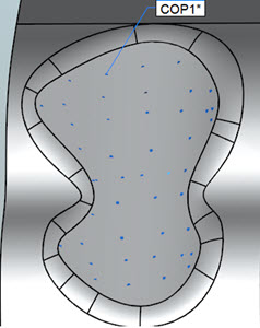
Method 1: Uncheck all three of the check boxes (Dots, Needles and Text) in the Display area of the Pointcloud Operator dialog box.
With all three of the Display check boxes unchecked, PC-DMIS projects the points onto the tesselated CAD model. The software computes the deviations, and then colors the Pointcloud accordingly.

Example of a Point Colormap using Method 1 (CAD model hidden)
This method allows you to create annotation points as well. For details on the annotation-related check boxes in the Pointcloud Operator dialog box, see the appropriate description in the "Surface Colormap" help topic starting with the "Create annotation points" check box description.
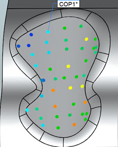
Method 2: Select any of the three check boxes in the Display area of the Pointcloud Operator dialog box.
When you select any or all of the Display check boxes, PC-DMIS projects the points onto the actual CAD model. The software computes the deviations, and then colors the Pointcloud accordingly. This process is more time-consuming and more accurate since the software projects the points onto the actual CAD model instead of on the tesselated CAD model. Because this operation is more time-consuming, it is best to first filter the pointcloud, or confine it to selected CAD faces.
To apply the POINT COLORMAP operation to a pointcloud,
click Pointcloud Point Colormap ( ) on the Pointcloud
toolbar, or select Insert | Pointcloud | Point Colormap
from the menu.
) on the Pointcloud
toolbar, or select Insert | Pointcloud | Point Colormap
from the menu.
The recommended process when creating a point colormap using dots, needles and/or text (Method 2) is:
Clean the data or select just those surfaces where you want the point colormap.

Use the DISTANCE type setting from the Filter COP Operator to filter the data.
Create the point colormap.
Example of the recommended steps to apply a point colormap
The Point Colormap operator has these properties:
Tolerances - Use this property to set the upper (plus) and lower (minus) tolerance values:
Plus - The upper tolerance value
Minus - The lower tolerance value
Use dimension color scale check box - When you select this check box, the software uses the Dimension Colors Bar to define the color bar for the Point Colormap color properties. For details on the Dimension Colors Bar, see "Using the Dimension Colors Window (Dimension Colors Bar)" in the "Using Other Windows, Editors, and Tools" chapter of the PC-DMIS Core documentation.
Edit Color Bar - If you do not select the Use
dimension color scale check box, the software enables the Edit Color Scale button. When you click this button,
the functionality to dynamically change the color, scale and threshold
of the surface and point colormap properties becomes available through
the Color Scale Editor dialog box. For details,
see the "Edit the Color Scale"
topic.
Dots - This option allows the use of colored dots.
Size - This option defines the size of the dots.
Needles - This option allows the use of scaled deviations (using the Scale value below) as a colored line segment normal to CAD.
Scale - This option defines the scale value PC-DMIS uses for the needle representation.
Text - This option defines the numerical value of the deviation.
Max distance - The software only includes points that fall within the Max distance value as part of the colormap. Note that if this value is too small, you may not see all the expected colored deviations. A good rule of thumb is to set this value slightly larger (10%, for example) than the largest deviation.
Thickness - This allows you to add a thickness value to deviations on the colormap. This is useful if you want to add a material thickness to a CAD surface model.
The following three annotation point check box options are only available if you DO NOT select the Dots, Needles, and Text check boxes. Also, the CAD model must be visible in order to create annotation points.
Create annotation points check box - For details on this check box, see the "Create annotation points" description in the "Surface Colormap" help topic.
Create MinMax annotations check box - For details on this check box, see the "Create MinMax annotations" description in the "Surface Colormap" help topic.
Show annotation points check box - When you select this check box, the software displays all annotation points.

Example of Point Colormap with annotations
Click Create to insert a COP/OPER,POINT COLORMAP command into the Edit window.
For example:
COPPCOLMAP1=COP/OPER,POINT COLORMAP,PLUS TOLERANCE=0.0394,MINUS TOLERANCE=-0.0394,THICKNESS=0,
SHOW DOTS=YES,DOT SIZE=0.0787,SHOW NEEDLES=YES,NEEDLE SCALE=10,SHOW LABELS=YES,
SIZE=50023
REF,COP2,,
Colormaps in the Report
For information on how the software shows colormaps in the report, see "Colormaps and the CadReportObject" in the "Reporting Measurement Results" chapter of the PC-DMIS Core documentation.
More: