Data filtering allows real-time filtering of the data. It removes the data as you scan.
You can click the Collapse
button  to hide sections
of the Laser Data Collection Settings dialog
box or click the Expand button
to hide sections
of the Laser Data Collection Settings dialog
box or click the Expand button  to display hidden sections
of the dialog box.
to display hidden sections
of the dialog box.
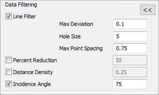
The Data Filtering section provides these options:
Line Filter - Select this check box to enable real-time filtering for individual lines. It provides smoothing and point reduction of incoming data from the laser sensor.
Mark the Line Filter check box to enable these options:
Max Deviation - As the software evaluates each incoming scan line, the software can move or smooth points in relation to their neighboring points. This setting defines the maximum allowed value that the software can move or smooth a point.
Hole Size - This setting defines the minimum hole or gap size during a scan. When PC-DMIS evaluates a scan line and detects a hole or gap of this size (or larger), the filter treats the scan segments as separate lines. In most cases, you can set the Hole Size value to the size of the smallest hole on the physical part.
Max Point Spacing - This setting defines the maximum distance between two consecutive points that the software uses when it analyzes the incoming scan data to reduce the number of points. If the scan surface is curved, the resulting point spacing is typically smaller than the Max Point Spacing value.
When this parameter is set to zero, no point reduction takes place. Typically, you should set this value to less than 1/3 of the hole size.
The Max Point Spacing setting determines the resolution of the scanned points. For most parts, you can use the default values from the table below. To obtain higher resolution when scanning parts with small details, you can use a smaller Max Point Spacing. A smaller Max Point Spacing results in fewer filtered points being scanned and increases the total COP size.
|
Max Point Spacing |
Large Details |
1 mm / 0.03937 inch |
Default |
0.75 mm / 0.02953 inch |
Small Details |
0.5 mm / 0.01968 inch |
Fine Details |
0.25 mm / 0.00984 inch |
Percent Reduction - This option removes a percentage of the pointcloud data collected.
Select the Percent Reduction option, and in the box to its right, type a percentage value between 0-100 inclusive. The value is the percent of the collected pointcloud data that you want the software to filter out. If you enter zero, no filtering takes place.
Click OK to apply this to your measurement routine.
Distance Density - This option filters the data based on the point distance value. If the distance between a point and its neighboring points is less than this value, the software discards the point. This option becomes available if you select the Points option in the Pointcloud Display section of the dialog box.
Select the Distance Density option and in the box to its right, type a distance value in the measurement routine's units. Values that are greater than or equal to zero are valid. 1 mm is the default value. If your measurement routine uses inches, the software converts 1 mm to inches.
Click OK to apply the filtering.
Incidence Angle - This option filters out all scanned points that have an incident angle greater than the entered value. The Incidence Angle check box is marked by default with a default value of 75. The angle is calculated between the estimated surface normal and the scan direction of the laser sensor. The smaller the value, the more points are filtered out.
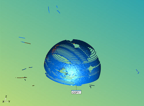
Shiny sphere with no incidence angle applied
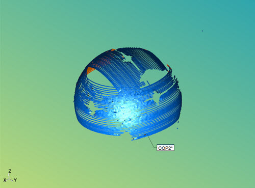
Shiny sphere with incidence angle on at default value 75
You can apply the Incidence Angle filter in real-time while scanning. During the scan process, the software determines the angle of the scan line that is relative to the measured surface. The software then automatically removes and discards any points that are greater than the specified angle.
The Incidence Angle option is not available if you are using the HP-L-10.10 laser sensor.
More: