Based on your current feature type, this area's content changes to include any of these items:
Point: This property specifies the XYZ values for Surface or Edge Point features.
Start: This property specifies the XYZ values for the start point of a Line feature.
End: This property specifies the XYZ values for the end point of a Line feature. This is only available when you set the Bounded property of the "Measurement Properties Area" to Yes.
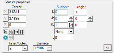
Center: This property specifies the XYZ values for the center of a Circle, Round Slot, Square Slot, or Profile 2D feature.
Surface: This property specifies the IJK values for the surface vector of any vision Auto feature.
Edge: This property specifies the IJK values for the edge vector for an Edge or Line feature. The Edge Point vector points away from the edge.
Angle: This property specifies the IJK values for the angle vector for a Round or Square Slot feature. The angle vector defines the feature's centerline. The feature centerline and normal vector must be perpendicular to each other. This value also specifies the reference vector for start and end angles for Circles (Arcs).
Thickness Type: This property defines how PC-DMIS applies a thickness to Surface or Edge values of a feature. The options are:
Theo - PC-DMIS applies the thickness as a theoretical value.
Actl - PC-DMIS applies the thickness as an actual value.
None - PC-DMIS does not apply a thickness.
T: This property specifies the thickness distance to apply to the Surface or Edge value of a feature, depending on the thickness type. This value is not available if you select None for the Thickness Type.
Length: This property specifies the length for Lines, Notch Slots, Round Slots, or Square Slots.
Bounded: When you select Yes, this property specifies the End property is available in the "Feature Properties Area" to define the end point of a Line feature.
Inner/Outer: This property specifies whether Circle, Square Slot, Round Slot, Notch Slot, Ellipse, and Polygon features are inner or outer features.
Diameter: This property specifies the diameter of a Circle or Polygon feature. The diameter for a polygon defines an inscribed circle within the polygon.
Major Diam: This property specifies the diameter of the long axis of an Ellipse feature.
Minor Diam: This property specifies the diameter of the short axis of an Ellipse feature.
Width: This property defines the width for Round Slots, Square Slots, or Notch Slots.
Num Sides: This property specifies the number of sides for a Polygon feature (3-12).
Feature Properties - Control Buttons
Vision Buttons |
Description |
|---|---|
|
This button switches between Polar and Cartesian coordinate system. |
|
When you select an axis (X,Y, or Z) from one of the Point or Start boxes and click this button, PC-DMIS finds the closest CAD element in the Graphic Display window to that axis. This option is only available for Surface Point, Edge Point, and Line features. |
|
This button reads the probe tip's position (stage position) and inserts it into the X, Y, and Z boxes. If you are on the Gage toolbox page and you press this button, PC-DMIS uses the Gage center point instead of the stage position. |
|
This button snaps a supported auto point feature to the 3D grid display in the Graphic Display window. For details, see "Snap to Grid" in the "Creating Auto Features" chapter in the PC-DMIS Core documentation. |
|
This button measures the selected feature when you click Create. |
|
This button determines whether or not PC-DMIS automatically re-measures the feature a second time once the feature has been measured. It uses the measured values from the first measurement as the target locations for the second measurement. |
|
This button pierces all surfaces along the XYZ point and IJK vector, looking for the closest point. The software displays the surface normal vector as the IJK NOM VEC, but the XYZ values do not change. This option is only available for Surface Point. |
|
This button reverses the direction of the I, J, K vector. |
|
This button reads and applies vector values based on your vision machine's vectors. |
|
This button causes the current edge vector and surface vector to switch vectors with each other. |


