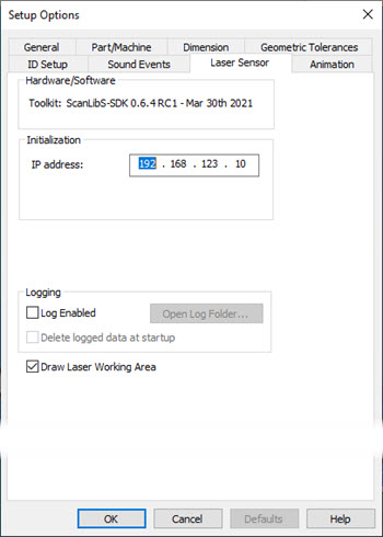
Open the Setup Options dialog box (Edit | Preferences | Setup) and click the Laser Sensor tab to show the options for your camera.
Setup Options dialog box - Laser Sensor tab example for the HP-L-10.10 sensor
Hardware/Software Area
This area displays the current HP-L-10.10 toolkit version.
Initialization Area
You can use the IP address box to define the IP address of the HP-L-10.10 controller.
Logging Area
Logging area - You can use this area to generate text-based log files that contain communication results between PC-DMIS and the laser sensor when the measurement routine executes. The information it sends to the log files includes scans, nominals of calculated features, and so on. Hexagon Technical Support can use these files to resolve issues that may involve your laser sensor.
Logging stores debug information on your machine which may slow down normal operations. You should keep logging turned off for normal operations and only turn it on for the time that you need to capture debug information. When done, you should always turn it back off.
Log Enabled - This check box enables or disables data sent to the log files.
Open Log Folder - This button opens up the folder that contains your log files.
Typically, PC-DMIS stores these files in the "C:\ProgramData\Hexagon\PC-DMIS\2022.2\NCSensorsLogs\" folder.
Delete logged data at startup - This check box deletes the logged data files from the log folder whenever you restart PC-DMIS.
Draw Laser Working Area Check Box
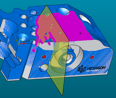
If you select the Draw Laser Working Area check box, the HP-L-10.10 probe parameters draw the trapezoid with the correct dimensions. This functionality helps with simulation in Offline mode. This feature is available for laser Auto features and laser scans.
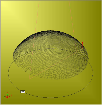
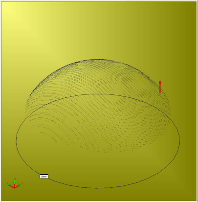
For a laser scan, the trapezoid that represents the working area of the laser is shown as the start point. The trapezoid moves according to the simulation of the laser stripes. Here's an example of the trapezoid when you click the Simulate button:
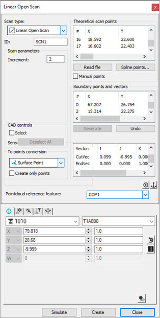
Example of Linear Open Scan dialog box for the HP-L-10.10 sensor
Example of linear open scan using the HP-L-10.10 sensor, mid-scan
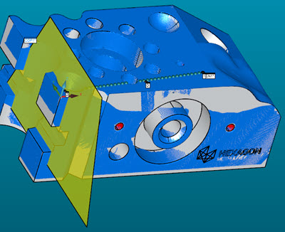
Example of linear open scan using the HP-L-10.10 sensor, scan completed
If you change the sensor-based clipping settings (located on the Laser Clipping Region Properties tab), PC-DMIS updates the trapezoid.
HP-L-10.10 Properties
You can adjust the scan properties for the HP-L-10.10 sensor from the HP-L-10.10 Properties tab on the Probe Toolbox.
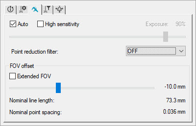
Auto check box and Exposure slider (UD mode) - The HP-L-10.10 sensor offers you two different acquisition modes (Auto and User-defined) to acquire a pointcloud with the highest quality. By default, both modes measure with a frequency of 300 Hz.
When you select the Auto check box, you are in Auto mode. Auto mode is a high dynamic range. It allows you to measure different surfaces with different surface colors and characteristics without the need of adjusting any settings.
User-defined (UD) mode is active when you do not select the Auto check box. PC-DMIS enables the Exposure slider. The UD mode has a low dynamic range but has the best accuracy in terms of dispersion. In UD mode, you must adjust the exposure setting manually with the Exposure slider, or you can use the auto gain function which automatically determines the correct exposure setting for the surface to be measured. In UD Mode, it is difficult to measure different surfaces with different surface characteristics at the same time. You need to adjust the exposure level for each surface variation.
High sensitivity check box - Select this check box if you need to scan highly glossy blue or black parts that are not sufficiently reflective.
Point Reduction Filter list - This list determines whether or not PC-DMIS filters points along the scan line. You can select the desired percentage of total points to filter. If you select the OFF option, PC-DMIS acquires the complete data set without any filtering.
 Example
of Point Reduction Filter Set to OFF
Example
of Point Reduction Filter Set to OFF
Example
of Point Reduction Filter Set to 50%
Extended FOV check box and slider - Select the Extended FOV check box to extend your field of view (FOV) measurement range an extra 30 mm. When you enable this option, PC-DMIS triggers a new scaling for the Extended FOV slider. This allows you to adjust the standoff from -30 to 60 mm. As soon as you move the slider to the Extended FOV location, the software highlights the background yellow. This notifies you that you can expect a higher dispersion when the standard FOV is left. If you have laser Live View active with Extended FOV enabled, PC-DMIS adjusts the FOV accordingly.
Example with no Extended FOV
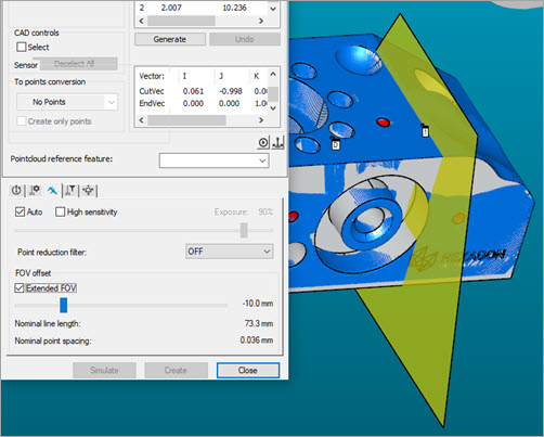
Example with Extended FOV
If you create a scan using the Standard FOV (the Extended FOV check box is not selected) and later edit that scan with the Extended FOV check box selected, the scan path remains the same. All subsequent executions of the scan are done using the Standard FOV.
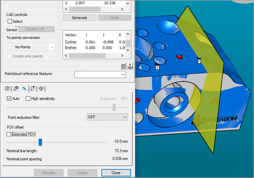
You can use the slider to change the center of the field of view for the scan. Here's an example of the same image above without the Extended FOV selected, but the FOV offset changed from -10.0 mm to 0 (zero):
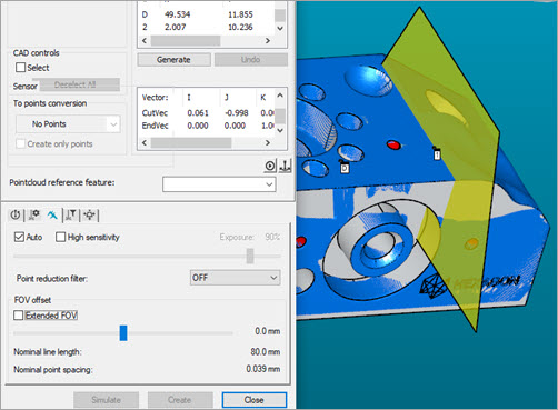
The Nominal line length and Nominal point spacing values dynamically change based on the position of the FOV slider.
More: