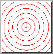
The Radius Chart gage can be used to determine the Center Location (X and Y) as well as the Spacing between concentric circles as read form the Gage tab of the Probe Toolbox or the corner of the Vision tab.
|
The Radius Chart gage can be used to determine the Center Location (X and Y) as well as the Spacing between concentric circles as read form the Gage tab of the Probe Toolbox or the corner of the Vision tab. |
For information on controlling the Circle gage, see the "Rotating, Sizing, or Moving Gages" topic.
Radius Chart Example
To check to see if circular hole pattern is concentric to a center hole:
Open the Probe Readout window (CTRL + W).
From the Probe Toolbox, adjust the magnification and lighting as needed. See "Probe Toolbox: Magnification tab" and "Probe Toolbox: Illumination tab".
From the Gage tab of the Probe Toolbox, select the Circle Gage option from the drop-down list.
From the Gage tab, double-click the Diameter box, and type the nominal diameter of 8.000.
Move the machine so the center hole is within the FOV. When the machine is close, you can optionally drag the Circle gage to the exact center using the mouse.
Click the Zero
Readouts DXYZ button  on the Gage
tab. This zeroes the DX, DT, and DZ values.
on the Gage
tab. This zeroes the DX, DT, and DZ values.
Change the gage type to Radius Chart Gage.
From the Gage tab, double-click the Spacer box, and type the nominal value of 1.000.
Drag the Radius gage such that is concentric to the pattern.
Read the X and Y values from the Probe Readout DX and DY values.