
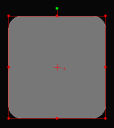
The Rectangle gage can be used to determine the Rectangle Center (X & Y) as well as the Height, Width, and Angle of the rectangle as read form the Gage tab of the Probe Toolbox or the corner of the Vision tab.
|
The Rectangle gage can be used to determine the Rectangle Center (X & Y) as well as the Height, Width, and Angle of the rectangle as read form the Gage tab of the Probe Toolbox or the corner of the Vision tab. |
For information on controlling the Cross hair gage, see the "Rotating, Sizing, or Moving Gages" topic.
Rectangle Gage Example
To measure the size and location of a rectangle from the center of a circular hole pattern:
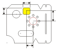
Ensure that the part is physically square on the inspection machine. See "Creating an Alignment".
Open the Probe Readout window (CTRL + W).
From the Probe Toolbox adjust the magnification and lighting as needed. See "Probe Toolbox: Magnification tab" and "Probe Toolbox: Illumination tab".
From the Gage tab of the Probe Toolbox, select the Circle Gage option from the drop-down list.
From the Gage tab, double-click the Diameter field and type the nominal diameter of 8.000.
Move the machine so the 8mm center hole is within the FOV. When the machine is close, you can optionally drag the Circle gage to the exact center using the mouse.
Click the Zero
Readouts DXYZ button  on the Gage
tab. This zeroes the DX, DT, and DZ values.
on the Gage
tab. This zeroes the DX, DT, and DZ values.
Change the gage type to Rectangle Gage.
Move the machine (with the Rectangle gage visible) over the rectangular opening. Again, drag the rectangle to the exact center and size the rectangle as needed.
Read the X and Y values from the Probe Readout (DX and DY) values.
Read the Height and Width values as displayed in the corner of the Live View. This value is also found in the Gage tab of the Probe Toolbox.