For details on extracting Auto features from a Mesh, see the "Extracting Auto Features from a Mesh" topic in the PC-DMIS Laser documentation.
For details on extracting Auto features from a Pointcloud (COP), see the "Extracting Auto Features from Pointclouds" topic in the PC-DMIS Laser documentation.
You can construct a cone that is extracted from a scanned Pointcloud (COP) or Mesh.
To do this:
Ensure that your measurement routine has a Pointcloud (COP) or Mesh command.
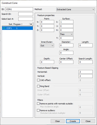
Open the Construct Cone dialog box (Insert | Feature | Constructed | Cone) or from the Constructed Feature toolbar (View | Toolbars | Constructed Features).
Construct Cone dialog box - Extracted Cone
From the Method list, select the Extracted Cone option.
From the Reference area, select the COP or Mesh that you want to use to extract the cone from.
Click on the CAD model or data to define the nominal or, in the Point section of the Feature properties area, type the nominal location in the X, Y, and Z boxes.
From the Surface section of the Feature properties area, define the surface vector in the I, J, and K boxes. In the Angle section, enter the corresponding vector angle values. You can use the Material Thickness Type list and the T box below it to type in a material thickness value. For details, see the "Use Thickness" topic in this documentation.
Select whether the extracted cone is an inner or outer cone type from the Inner/Outer list.
Enter the diameter and length of the cone in the respective boxes. The Diameter value defines the cone's initial diameter, and the Length value defines the length (height) of the cone's axis. The Length parameter is only valid as nominal. PC-DMIS does not perform an actual length measurement.
Enter the Angle value. This is the included angle of the cone.
Enter the Depth value. This parameter controls the location of the laser focal point in relation to the cone's outside diameter (outer cones) or the cone's center axis (inner cones). This allows you to control how the laser stripes fall on the cone's surface by specifying how far or close the laser is to the cone's surface. A depth of 0 (zero) causes this feature to be calculated at the surface plane height using data found at the lowest possible depth from the surface plane. A depth of any other value causes the software to perform the calculation at that depth.
Enter the Center Offset value. This value identifies the center location of where the laser starts to measure the cone. If you do not enter a Search Length value, this value defines where the measurement begins.
Enter the Search Length value. This value defines the distance from the Center Offset the laser measures for the cone. For example, if you have a Center Offset value of zero and a Search Length value of 20, the laser begins measuring +20 units from the Center Offset value.
PC-DMIS draws the extraction zone and centers it around the XYZ location point. This box defines the cylinder zone that PC-DMIS uses for the extracted cone. The yellow cylinder is the surface. The yellow cylinder is also the horizontal zone and the green cylinder is the vertical zone. The orange points are the candidate points that the extraction considers.
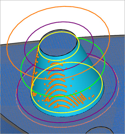
Example of an Extracted Cone showing the candidate points
From the Feature Based Clipping area, define the Horizontal and Vertical values. These values set the dimensions for the green extraction zone region. Consider part variability when you define the extraction zone.
Alternatively, you can clip data within an offset boundary around all the CAD elements on a surface with the CAD offset option. This is also called CAD segregation. For details, see the "CAD offset" section of the "Feature Based Clipping Parameters" topic in the PC-DMIS Laser documentation.
If you want to define the Ring Band offsets, click the Ring Band check box and enter the Inner Offset and Outer Offset values. For details on how the Ring Band works, see the "Ring Band Parameters" topic in the PC-DMIS Laser documentation.
If you want to apply any of the filters in the Filters area, select the available check boxes and enter an appropriate value. For details on the Filters area, see the "Filters" topic in the PC-DMIS Laser documentation.
Click the Create button. Based on the parameters that you specified in the dialog box, PC-DMIS does an analysis of the candidate points and returns (or extracts) the cone and projects it to the surface. Click the Close button to close the dialog box.
PC-DMIS creates the command in the Edit window:
CON1=FEAT/CONE,CARTESIAN,OUT
THEO/<69,90,13.995>,<0,0,-1>,30,13.995,8
ACTL/<68.873,89.926,13.994>,<0.0061449,0.0001119,-0.9999811>,30.367,13.995,7.893
DEPTH=0
CENTER OFFSET=6.998
SEARCH LENGTH=11.995
THEO_THICKNESS,0
USE CAD SEGREGATION=ON,CAD OFFSET=1
HORIZONTAL CLIPPING=3,VERTICAL CLIPPING=1
RINGBAND=OFF
USE OUTLIER REMOVAL=OFF
REMOVE POINTS WITH NORMALS OUTSIDE=OFF
CONSTR/CONE,EXTRACTED,REF=COP1
More: