For details on extracting Auto features from a Mesh, see the "Extracting Auto Features from a Mesh" topic in the PC-DMIS Laser documentation.
For details on extracting Auto features from a Pointcloud (COP), see the "Extracting Auto Features from Pointclouds" topic in the PC-DMIS Laser documentation.
You can construct a sphere that is extracted from a scanned Pointcloud (COP) or Mesh.
To do this:
Ensure that your measurement routine has a Pointcloud (COP) or Mesh command.
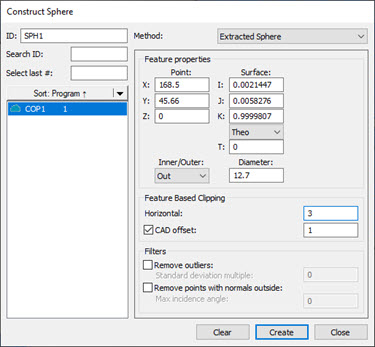
Open the Construct Sphere dialog box (Insert | Feature | Constructed | Sphere) or from the Constructed Feature toolbar (View | Toolbars | Constructed Features).
Construct Sphere dialog box - Extracted Sphere
From the Method list, select the Extracted Sphere option.
From the Reference area, select the COP or Mesh that you want to use to extract the sphere from.
Click on the CAD model or data to define the nominal or, in the Point section of the Feature properties area, type the nominal location in the X, Y, and Z boxes.
From the Surface section of the Feature properties area, define the surface vector in the I, J, and K boxes. In the Angle section, enter the corresponding vector angle values. You can use the Material Thickness Type list and the T box below it to type in a material thickness value. For details, see the "Use Thickness" topic in this documentation.
Select whether the extracted sphere is an inner or outer sphere type from the Inner/Outer list.
Type the diameter of the sphere in the Diameter box.
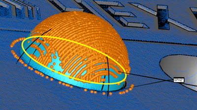
Example of a Constructed Extracted Sphere showing the candidate points
From the Feature Based Clipping area, define the Horizontal and Vertical values. This sets the dimensions for the extraction zone region. Consider part variability when you define the extraction zone.
Alternatively, you can clip data within an offset boundary around all the CAD elements on a surface with the CAD offset option. This is also called CAD segregation. For details, see the "CAD offset" section of the "Feature Based Clipping Parameters" topic in the PC-DMIS Laser documentation.
If you want to define the Ring Band offsets, click the Ring Band check box and enter the Inner Offset and Outer Offset values. For details on how the Ring Band works, see the "Ring Band Parameters" topic in the PC-DMIS Laser documentation.
If you want to apply any of the filters in the Filters area, select the available check boxes and enter an appropriate value. For details on the Filters area, see the "Filters" topic in the PC-DMIS Laser documentation.
Click the Create button. Based on the parameters that you specified in the dialog box, PC-DMIS does an analysis of the candidate points and returns (or extracts) the sphere and projects it to the surface. Click the Close button to close the dialog box.
PC-DMIS creates the command in the Edit window:
SPH1       =FEAT/SPHERE,CARTESIAN,OUTER
            THEO/<168.5,45.66,0>,<0.0021447,0.0058276,0.9999807>,12.7
            ACTL/<168.586,45.406,0.05>,<0.0021447,0.0058276,0.9999807>,12.781
            THEO_THICKNESS,0
            USE CAD SEGREGATION=ON,CAD OFFSET=1
            HORIZONTAL CLIPPING=3
            USE OUTLIER REMOVAL=OFF
            REMOVE POINTS WITH NORMALS OUTSIDE=OFF
            CONSTR/SPHERE,EXTRACTED,REF=COP1
More: