Select a Surface probe.
Open the Line Scan
dialog box from the menu (Insert | Scan | Line
Scan), or click the Line Scan button
 from the Tracker Measure toolbar.
To perform a Line Scan from the Line Scan dialog box and create the Line Scan command:
Select a Surface probe.
Open the Line Scan
dialog box from the menu (Insert | Scan | Line
Scan), or click the Line Scan button
from the Tracker Measure toolbar.
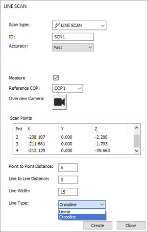
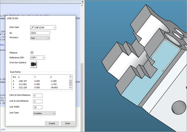
Line Scan dialog box
You can update the ID for your scan in the ID field or use the default name. This is the name of the scan command that PC-DMIS displays in the Edit window.
Select an accuracy option from the Accuracy Settings list of the Area Scan dialog box. The available options are: Standard, Fast, and Precise.
Select the Measure check box if you want to begin measurements immediately after you close the dialog box. This option is available when you run PC-DMIS in either Online or Offline mode as long as the definition exists on the CAD.
Select a COP from the Reference COP list. This is the COP that PC-DMIS stores the scanned data in. If you don't select a COP from the list, or if you enter one that is not yet created, PC-DMIS displays a prompt to ask if you want to create a new COP.
Click the Overview Camera button to open the Overview Camera window. You can use the window to define the region and settings for the scan. When done, click the "X" in the upper-right of the Overview Camera window to close it.
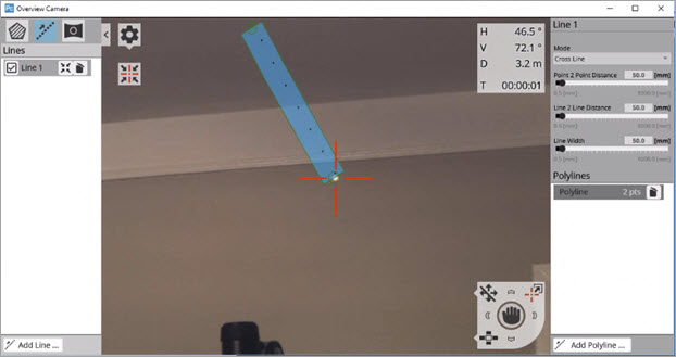
Example of the Overview Camera window
You define the Region settings in the Overview Camera window. PC-DMIS stores these settings in the Line Scan command. The Region settings include the Point 2 Point Distance, Line to Line Distance, and the Grow/Shrink Width.
For details on the Overview Camera window including the Region settings, see the appropriate Leica manual.
Type a value in the Point to Point Distance box. This option specifies the minimum distance between two consecutive points in a scan line.
Type a value in the Line to Line Distance box. This value specifies the minimum distance between two consecutive scan lines.
Type a value in the Line Width box. This value specifies the width of the drawn line on the CAD model in the Graphic Display window.
The ATS600 Line scan has two different modes which you can select from the Line Type list. For each mode, you can set the Start and End point, or multiple Start/End points to create a route.
The available modes are:
Linear - This mode is useful if you want to measure perimeters or lines. If the ATS600 is perpendicular to the measurement object and all you need to measure are lines, you can now draw them and set a value for the line width. This allows the beam to move through the different points using the fastest route instead of following each line exactly. If you need the tracker to follow a perfect line, then set the line width to its minimum value (0.5mm).
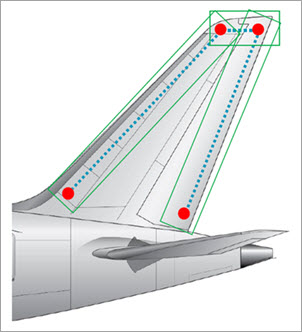
Example of a Line scan using the Linear Line Type
Crossline - This mode drives the ATS600 beam on a zig-zag route to collect points. This method is useful if you want to make pointcloud cross sections.
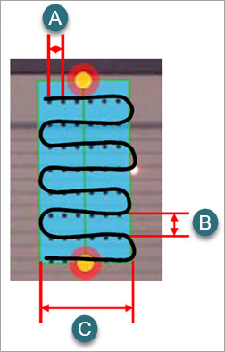
Example of a Line scan using the Crossline Line Type
A = Point to Point Distance
B = Line to Line Distance
C = Line Width
When creating a pointcloud Cross Section, set the Delta value to be within the Crossline width.
Click Create to add the Line Scan command into the Edit window, and then click Close to return to the PC-DMIS main screen.
Line Scan example
More: