The CWS can operate in different exclusive modes:
Distance mode (default)
Thickness mode
You can enable Thickness mode when you open the Thickness scan dialog box, or when you execute the command. The software disables Thickness mode when you close the dialog box, or when the execution of the command is complete.
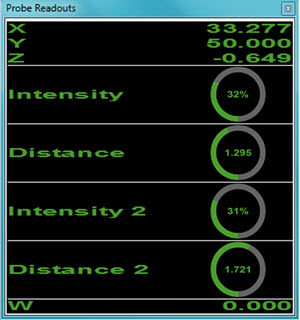
In Thickness mode, the software reports two pairs of values from the sensor's controller unit:
Distance1 and Intensity1
Distance2 and Intensity2
PC-DMIS displays these values in the Probe Readouts window when the Thickness scan dialog box is open or during execution.
To create a Thickness scan:
Ensure you are in DCC mode and that CWS is the active sensor.
Import your CAD model to define the sensor trajectory.
Open the Thickness scan dialog box (Insert | Scan | Thickness).
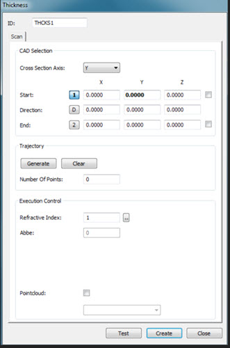
Thickness scan dialog box
Select the axis from the Cross Section Axis list. The options are X, Y, or Z.
Enter the Start, Direction, and End options, or click on the CAD model in the Graphic Display window to fill these values in automatically.
The Start and End check boxes allow the Start and End point mouse clicks to snap to the CAD edge. PC-DMIS generates a polyline from the selected Cross Section Axis and the first mouse click. You can then edit the Cross Section Axis from the Start field. The software automatically updates the generated polyline from the new user-defined coordinate.
From the Trajectory area, click the Generate button. The software generates the scan trajectory for the sensor, displays the number of generated points and updates the display in the CAD View.
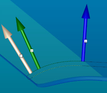
Example of a generated Thickness scan
Click the Clear button to remove the scan trajectory and values in the Start, Direction, and End fields.
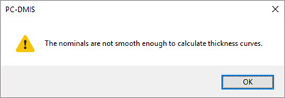
The primary curve nominal data must be smooth relative to the thickness. If it is not a smooth curve and you click the Generate button, the software displays an error message and does not generate points.
Edit the Refractive Index value if necessary. Click the Edit button to open the Select Material dialog box. You can then review or update the current values.
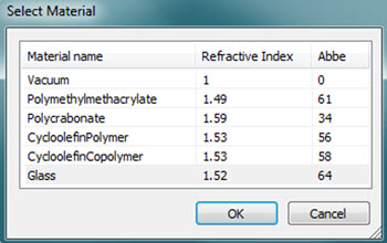
Select Material dialog box for Thickness scan
Select the Pointcloud check box if you want to include the scanned points into an existing Pointcloud (COP) command. Once you select this check box, enter the ID for the COP command or select it from the list. If a COP command doesn't exist, PC-DMIS prompts if you want to generate a new one. For details on Pointcloud operators, see "Pointcloud Operators" in the PC-DMIS Laser documentation.
More: