Defining The ClearanceCube
You can define the ClearanceCube in a measurement routine
with or without a CAD model.
Measurement Routine with CAD
To define a ClearanceCube in a measurement routine
with a CAD model, follow these steps:
Select Operation | Graphic
Display Window | ClearanceCube, or from the ClearanceCube
toolbar, click the Clearance Cube Definition
icon  . This opens
the ClearanceCube Definition dialog box.
. This opens
the ClearanceCube Definition dialog box.
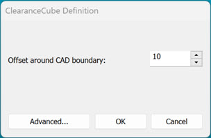
ClearanceCube Definition dialog box
Offset around CAD boundary
- Type an offset value in this box or use the up and down arrows to
increase or decrease the current value by one. Based on this value,
PC-DMIS draws the ClearanceCube around the CAD model the current distance
away from the part on all six sides. PC-DMIS uses the same units of
measurement as the measurement routine.
Advanced - This button
expands the dialog box from a single-tab to a multi-tabbed dialog
box. The tabs on the advanced dialog box include: Size and
Constraints.
This button then changes to read Simple.
Click the button again to display the simple dialog box.
You can use the advanced area to:
Customize the ClearanceCube offset along
each axis.
Define a ClearanceCube for a measurement
routine that does not use a CAD model.
Set the constraints for the ClearanceCube.
If you use the Advanced tab
to customize the size, the offset box in the simple definition dialog
box displays "N/A" routine.
OK - This button defines
and activates the ClearanceCube.
Cancel - This closes
the dialog box without saving the changes.
Type an offset value in the Offset
around CAD boundary box.
Click the Advanced
button to customize the size and constraints for the ClearanceCube.
Click OK to close
the dialog box.
Measurement Routine without CAD
To define a ClearanceCube in a measurement routine
without a CAD model, follow these steps:
Prerequisites
Create an alignment that controls all six degrees
of freedom of the part.
Set CAD = Part (Operation | Graphic Display Window | CAD Equals Part).
You must create an alignment and then set CAD Equals
Part even though you do not have a CAD model in your measurement routine.
If you don't complete the prerequisite steps before
you define the ClearanceCube, PC-DMIS displays an error that informs you
to complete the required steps.
Define ClearanceCube
Select Operation | Graphic
Display Window | ClearanceCube, or from the ClearanceCube
toolbar, click the Clearance Cube Definition
icon . This opens
the ClearanceCube Definition dialog box.
ClearanceCube Definition
dialog box
Click Advanced to
open the Size and Constraints
tabs on the ClearanceCube Definition dialog
box.
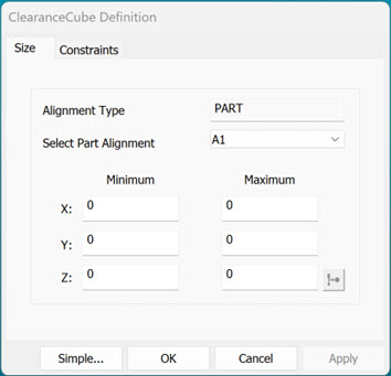
ClearanceCube Definition
dialog box - Advanced
In the Size tab,
from the Select Part Alignment list, select
the part alignment in which you want to define ClearanceCube.
In the Minimum and
Maximum area, type the location values for
the ClearanceCube in the Minimum XYZ and
Maximum XYZ boxes relative to the selected
alignment.
You must make sure that the
minimum value of each axis is smaller than the maximum value of the corresponding
axis.
Click OK to close
the dialog box. If you want to define a ClearanceCube and continue
to modify its definition, click Apply.
You cannot define a ClearanceCube from the STARTUP alignment.
PC-DMIS does not display this alignment in the STARTUP alignment list.
Re-import a CAD in a Measurement Routine with ClearanceCube
When you re-import a CAD model into a measurement routine
with a pre-defined ClearanceCube, you must consider these factors:
When you re-import a CAD
model into a measurement routine, PC-DMIS redefines the ClearanceCube
automatically. PC-DMIS uses the same offset boundary for each side as
defined in the original CAD model.
PC-DMIS redefines the ClearanceCube
by default with a 10 mm offset to the CAD model's boundary.
PC-DMIS 2023.2 and later
versions do not allow you to define a ClearanceCube with part alignment
if a CAD model is available. PC-DMIS redefines the ClearanceCube and displays
a message to inform you of the new ClearanceCube settings.