Quick Start Alignments
You can create various alignments with the Quick Start
interface for your portable device. The basic alignment examples provided
here relate directly to Leica reflectors and T-Probes, but the principles
are the same for all portable devices.
Example Plane-Line-Point Alignment with CAD and Reflectors
Import a CAD model. See "Importing
Nominal Data".
From the Quick Start
interface, select Alignments | Plane/Line/Point
.

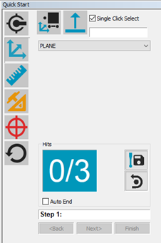
Quick Start showing Plane-Line-Point
Alignment
Follow the instructions provided by the Quick
Start interface to measure the alignment features.
While not aligned yet to your part, make sure to use
the Pulled Hits Method to take measurements.
For more information on "pulled hits", see the "Options
tab" topic in the "Leica
Interface" chapter.
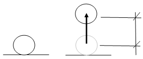
Take Hit (Ctrl + H) stores the current stationary measurement
internally. After you move the probe the vector distance, PC-DMIS calculates
the IJK vector between the first and second point and compensates the
offset of the resulting point accordingly.

Vector Distance depicted for reflector movement
Example Plane-Line-Line Alignment with CAD and T-Probe
Import a CAD model. For information, see "Importing
CAD Data or Measurement Routine Data" in the "Using
Advanced File Options" chapter in the PC-DMIS Core documentation.
From the Graphic Modes
toolbar, enable Program Mode ( ).
).
From the same toolbar, select the mode for
your CAD data:
Select Alignments | Plane/Line/Line
from the Quick Start interface.
Follow the instructions provided by the Quick
Start interface to measure the alignment features in Programming mode.

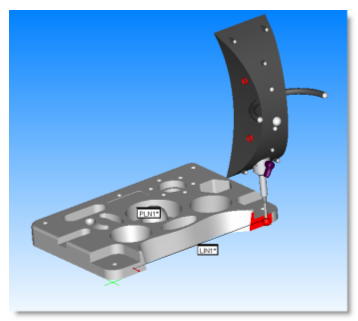
Measuring Alignment Features with a T-Probe
Once the software completes the measurement
routine, press Ctrl + Q or select the File | Execute
menu item to execute the routine.
While not aligned yet to your part, make sure to use
the Pulled Hits Method to take measurements.
For more information on "pulled hits", see the "Options
tab" topic in the "Leica
Interface" chapter.
Creating Alignments Offline
It is also possible to create an alignment offline
using features that were previously measured. To do this, select the features
from the Edit window instead of measuring them from the Quick Start interface.


 ).
).

