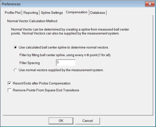
Use the Compensation tab to specify how to calculate normal vectors. To determine vectors, compensate for the probe ball radius or use the normal vectors that your measuring system establishes.

Preferences dialog box - Compensation tab
Use calculated ball center spline to determine normal vectors option - If you select this option, PC-DMIS Blade estimates the normal vector for each measured point. The first step in this process is to create a spline from the ball center data using a reduced set of points.
The reduction is determined by specifying the filter spacing. For example, if you use a filter spacing of 3, every third point computes the initial spline. This is done to help create a smoother spline that computes the surface normal vectors. These vectors remove the probe radius and also slide the compensated point back into the section plane.
Use normal vectors supplied by the measurement system option - If you select this option, PC-DMIS Blade uses the normal vectors that your measuring system calculated. These vectors are usually not very accurate.
Resort Ends after Probe Compensation check box - Specifies whether the probe-compensated points at the leading and trailing edges should resort after compensation. For more information about probe compensation, see "About Probe Compensation in PC-DMIS Blade" below.
Remove Points From Square End Transitions check box - For square-end blades, a condition exists that does not occur for normal, rounded blade ends. First, part of the point compensation involves trying to find which point on the nominal curve is representative of a point that is being compensated.
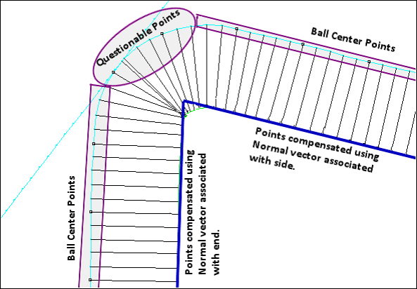
When the point is found, PC-DMIS Blade borrows the K component of its normal vector and uses that as part of the compensation (see the image below). For square ends, an abrupt change occurs when transitioning from the side to the end of the blade. But when the blade is scanned, the probe rotates around the sharp corner resulting in a round area in the ball center points as it scans around the corner. PC-DMIS Blade tries to determine what the K component of these points are, but they really are not defined because of the abrupt nominal change.
To instruct PC-DMIS Blade to throw those points away and not attempt calculations with them, select this check box.

Example showing questionable points on a square-end blade
About Probe Compensation in PC-DMIS Blade
Probe compensation is the act of moving the calculated center of a probe tip to the surface it measured. PC-DMIS Blade assumes that the blade is locally flat by considering the small patch around the point to be planar.
PC-DMIS Blade uses the normal vector of this plane to compensate for the radius of the probe to determine the location where the probe made contact with the part surface. The contact point is probably not in the section plane, so the algorithm slides the contact point along the local plane until it sits in the section plane. To perform these steps, PC-DMIS Blade needs to determine the approximate vector of the local plane at each point. The software can determine the I and J components of the plane vector by evaluating the 2D ball center spline.
PC-DMIS Blade estimates the K component of each point’s plane vector by finding the corresponding point on the nominal curve and uses its K value (interpolated using the two closest nominal points). This K value is combined with the I and J values determined above to construct approximate surface normal vector.
More: